EasyManuals Logo

Allied Telesis AlliedWare Plus GS980MX Series User Manual

Allied Telesis AlliedWare Plus GS980MX Series
254 pages
To Next Page IconTo Next Page
To Previous Page IconTo Previous Page
Page #102 background imageLoading...
Page #102 background image
Chapter 4: Installing the Switch on a Table
102
Installing the Bumper Feet
The switch comes with four bumper feet in the accessory kit. The feet,
which are reusable, are used when installing the switch on a table. If they
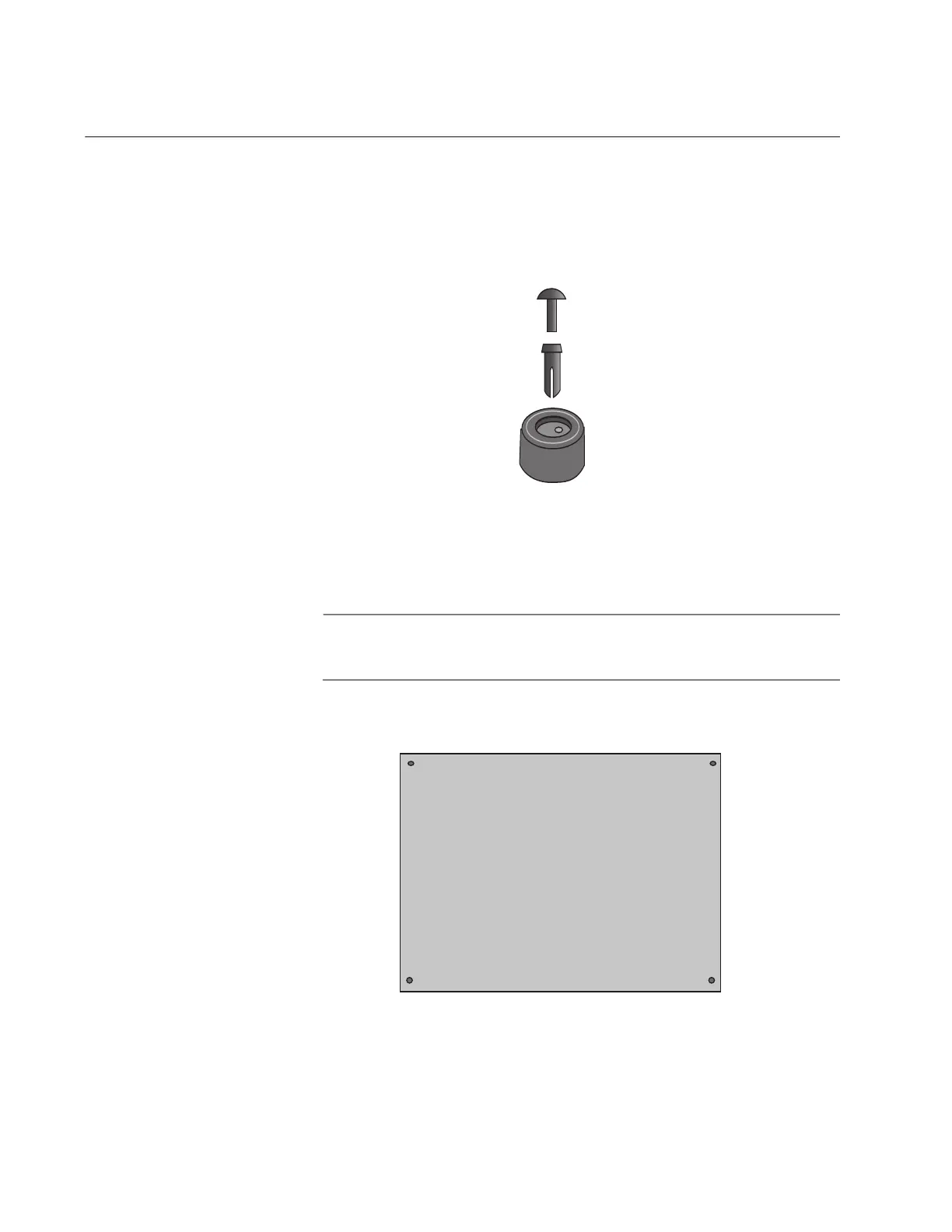
are already assembled, disassemble them by removing the rivets and rivet
housings from the bumper feet. Refer to Figure 42.
Figure 42. Parts of the Bumper Feet
The holes in the base of the switch for the bumper feet are shown in
Figure 43.
Note
Although you cannot stack the switches on top of each other, they
can be placed next to each other.
Figure 43. Holes for Bumper Feet
Rivet
Rivet Housing
Bumper Foot
Rear of Chassis
Front of Chassis

Table of Contents

Questions and Answers:

Question and Answer IconNeed help?

Do you have a question about the Allied Telesis AlliedWare Plus GS980MX Series and is the answer not in the manual?

Allied Telesis AlliedWare Plus GS980MX Series Specifications

General IconGeneral
BrandAllied Telesis
ModelAlliedWare Plus GS980MX Series
CategorySwitch
LanguageEnglish

Related product manuals