2-6 Line Sweep Measurements Cable and Antenna Analyzer
2-18 PN: 10580-00241 Rev. B Cable & Antenna Analyzer MG
Distance-To-Fault (DTF)
DTF reveals the precise fault location of components in the transmission line system. This
test helps to identify specific problems in the system, such as connector transitions, jumpers,
kinks in the cable or moisture intrusion.
To measure the distance of a cable, DTF measurements can be made with an open or a short
connected at the end of the cable. The peak indicating the end of the cable should be between
0 dB and 5 dB. An open or short should not be used when DTF is used for troubleshooting
because the open/short will reflect everything and the true value of a connector might be
misinterpreted and a good connector could look like a failing connector.
A 50 Ω load is the best termination for troubleshooting DTF problems because it will be 50 Ω
over the entire frequency range. The antenna can also be used as a terminating device but the
impedance of the antenna will change over different frequencies because the antenna is only
designed to have 15 dB or better return loss in the passband of the antenna.
DTF measurement is a frequency domain measurement and the data is transformed to the
time domain using mathematics. The distance information is obtained by analyzing how
much the phase is changing when the system is swept in the frequency domain. Frequency
selective devices such as TMAs (Tower Mounted Amplifiers), duplexers, filters, and quarter
wave lightning arrestors change the phase information (distance information) if they are not
swept over the correct frequencies. Care needs to be taken when setting up the frequency
range whenever a TMA is present in the path.
Because of the nature of the measurement, maximum distance range and fault resolution is
dependent upon the frequency range and number of data points. DTF Aid shows how the
parameters are related. If the cable is longer than DMax, the only way to improve the
horizontal range is to reduce the frequency span or to increase the number of data points.
Similarly, the fault resolution is inversely proportional to the frequency range and the only
way to improve the fault resolution is to widen the frequency span.
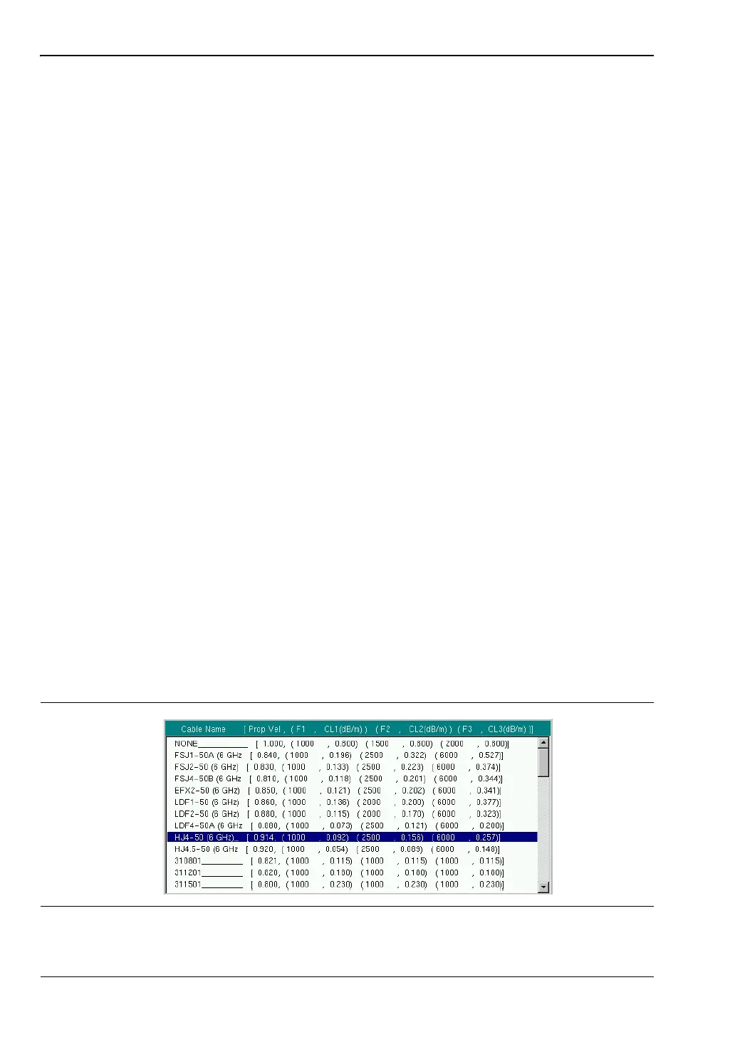
The instrument is equipped with a cable list (Figure 2-13) including most of the common
cables used today. Once the correct cable has been selected, the instrument will update the
propagation velocity and the cable attenuation values to correspond with the cable. These
values can also be entered manually. Custom Cable lists can also be created with Master
Software Tools and Uploaded into the instrument. Incorrect propagation velocity values affect
the distance accuracy and inaccurate cable attenuation values affect the accuracy of the
magnitude value.
Figure 2-13. Cable List