CPS100 SERIES OPERATION MANUAL
SECTION 13:
Error Messages & Troubleshooting
Entire Contents Copyright 2018 by Adaptive Power Systems, Inc. (APS) • All Rights Reserved • No reproduction without written authorization from APS.
APS CPS100 Series Power Source Operation Manual Page 207 of 231 PN 160953-10
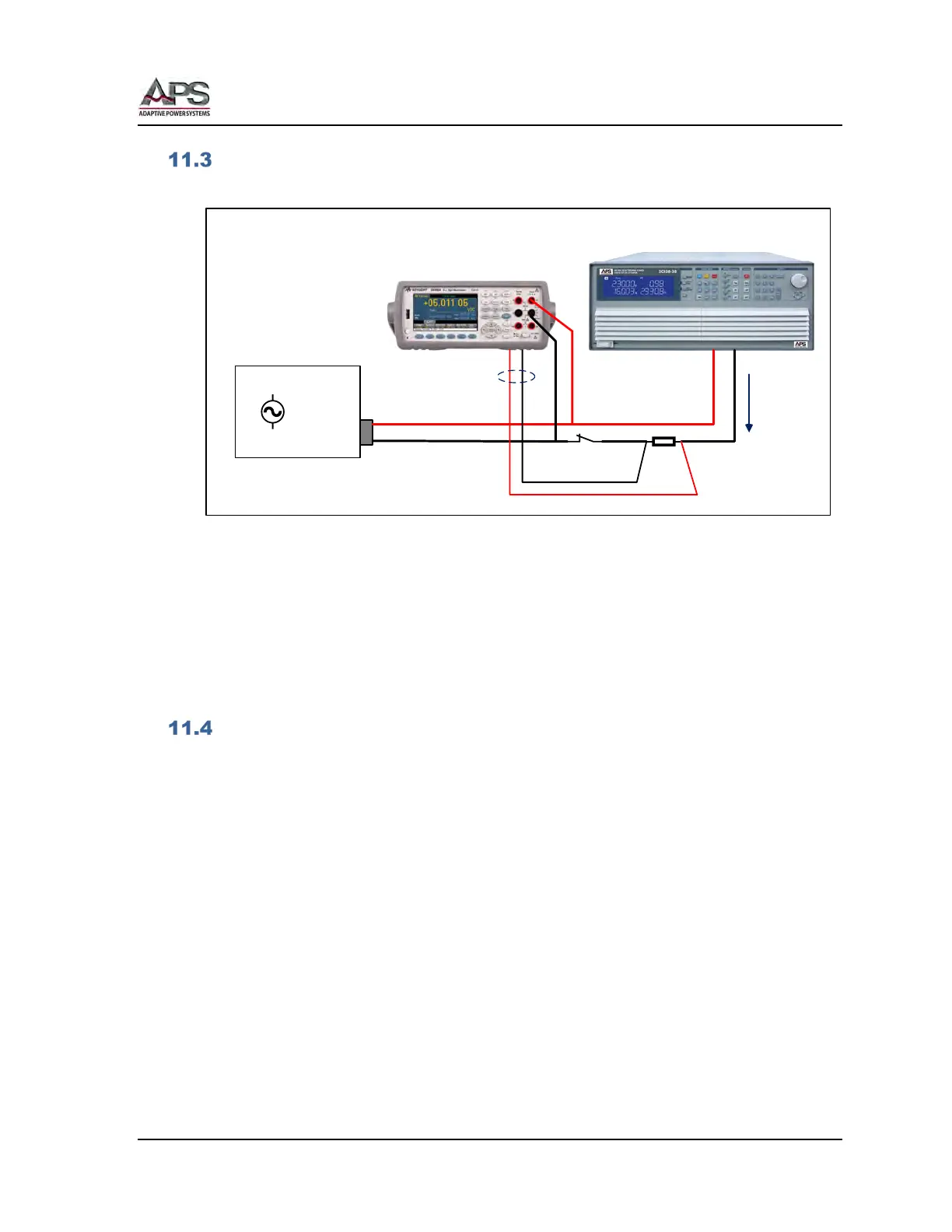
Calibration Equipment Setup
The calibration equipment must be connected as shown in the diagram below.
AC
SWITCH
SHUNT
DMM
REAR INPUTS
CURRENT
DMM
Front input: V meas.
Rear input: I meas.
R Load or
Electronic Load
CPS
100 Series
Power Source
L
N
+
_
Figure 11-1: Calibration Equipment Setup
Notes:
1. The DMM is used for both voltage and current measurements, requiring the
operator to switch between front and read inputs. Alternatively, a second DMM
may be used for current measurements instead if this is preferred.
2. The switch shown is used to disconnect any load when performing voltage
calibrations.
Calibration Procedure
The power source can be calibrated from the front panel. There are no manual calibration
adjustment inside the unit so there is no need to remove the top cover.
The following items require routine calibration:
• Output Voltage Setting
• Voltage Measurement
• Current Limit Setting
• Current Measurement
The user can perform his own calibration if needed. For traceability, it is recommended a
calibration lab perform these calibrations.