CHAPTER 5, CUSTOMIZING THE EFD1000 PFD
EFD1000 PFD Pilot’s Guide
Page 5-10 A-01-184-00 REV B
EFD1000 PFD Pilot’s Guide
EFD1000 PFD Pilot’s Guide
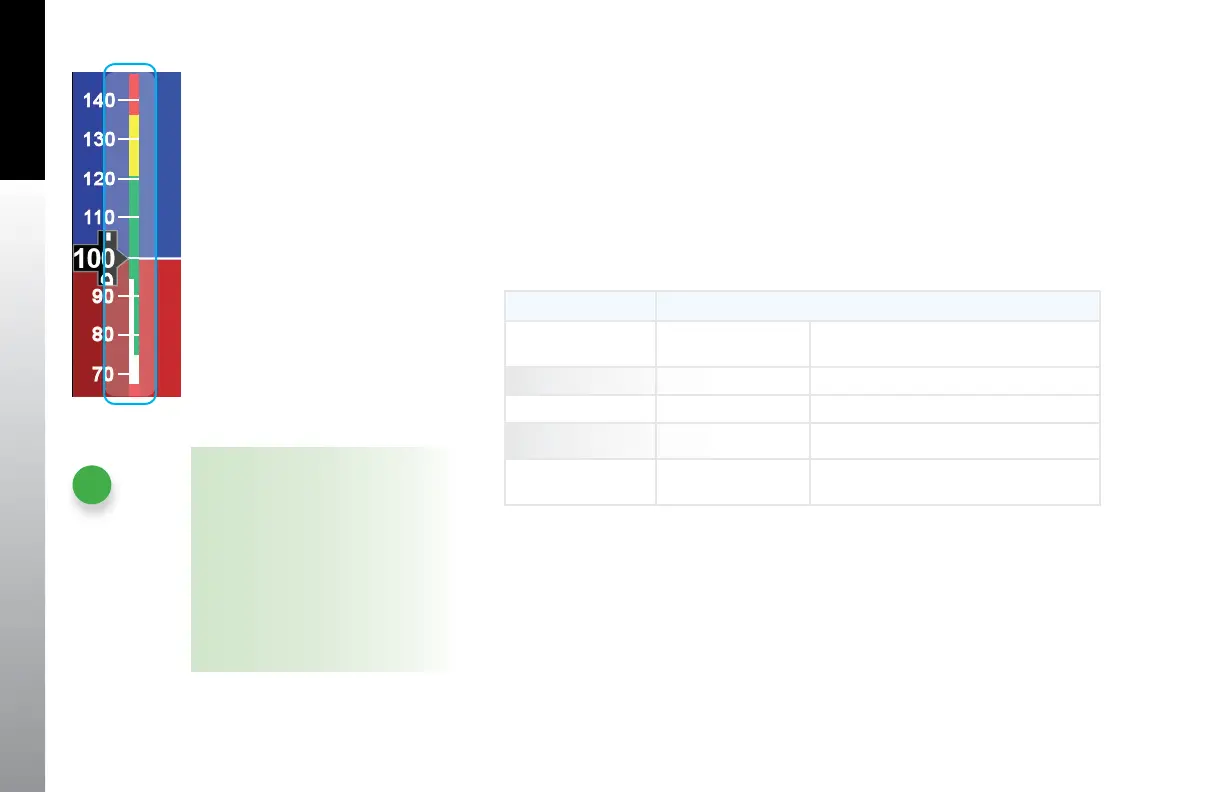
The EFD1000 PFD uses colored speed bands, colored speed markers, and textual
labels to help the pilot recall V-speed settings and limits. The speed band markings are
determined by the Federal Regulations, and correspond to the aircraft limiting speeds
that are identied in the Aircraft Flight Manual. They have a range between two speeds,
that are pre-set at installation as outlined in Table 5-10 and shown in Figure 5-18.
Speed markers are also pre-set during installation, indicating aircraft specic speed
settings, where applicable. The textual V-speed labels are pilot adjustable.
BAND COLOR SPEED RANGE
Red Band (High
Speed)
Vne - top tape Never Exceed
Yellow Band Vno – Vne Caution Range
Green Band Vs – Vno Normal Operating Range
White Band Vso – Vfe Flap Operating Range
Red Band (Low
Speed)
Bottom of tape – Vs0 Disabled on the ground and during takeo
Table 5 -10 Speed Band Ranges
Figure 5-18
Speed Bands
NOTE
On aircraft without aps the white
band is disabled, and the green band
is shown full width, as there isn’t an
applicable Flap Extend (Vfe) or Full
Flap Stall (Vso) speed. These two
speeds are set to the same speed
as the No Flap Stall (Vs) speed. This
gives the white band a value of zero,
eectively disabling it.