2 - 22
Basics of Assembly
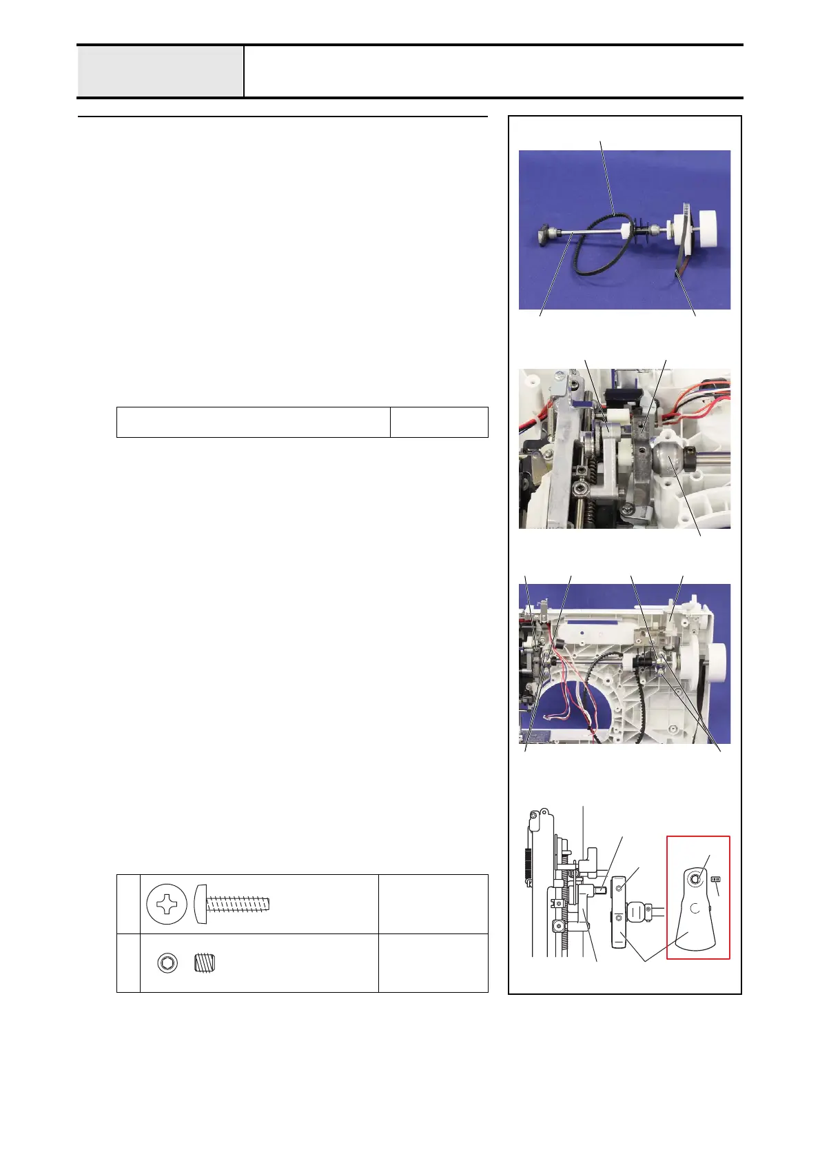
Needle bar, presser mechanism / Upper shaft mechanism
2 Attachment of Upper shaft assy
1. Pass the T belt 420-5GT-6 (timing belt) 2 and timing belt 372-2GT-6
(motor belt) 3 to the upper shaft assy. 1.
2. Set the thread take-up counter weight 5 to the needle bar crank rod assy.
4.
3. Set the upper shaft bushing 6 to the positioning part of the rear cover
assy..
4. Set the 2 upper shaft bearing pressers 78 to the rear cover assy. with the
4 screws 1.
*Key point
• Check that the bobbin winder assy. 9 is on the left side.
• Attach the left upper shaft bearing presser 7 so that the
projecting part of 7 is positioned at the upper right. And attach
the right upper shaft bearing presser 8 so that the projecting
part of 8 is positioned at the lower shaft.
5. Align the D-cut face of the needle bar crank rod assy. 4 with the screw
hole on the thread take-up counter weight 5, and tighten the screw 2.
→ Refer to 3 - 63 "Assembly of Upper shaft assy".
Apply OILER to the matching section of the upper shaft
and the upper shaft bushing.
1 - 2 drops
XZ0206***
1
Torque
1.18 – 1.57 N·m
2
Torque
1.18 – 1.57 N·m
2
4
D-cut face
5
D-cut face
2
2
31
4 5
6
2
1
87
1
9
Giza Tite
M5X16
Set Screw, Socket (FT)
M5X5
 Loading...