2 - 27
Electrical parts and motors
Basics of Assembly
Basics
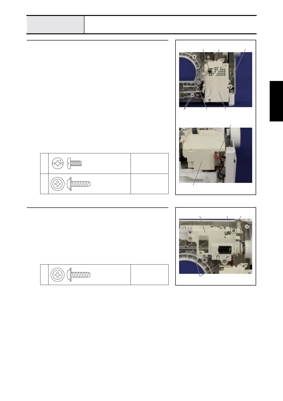
5 Attachment of Power supply unit
1. Set the power supply unit 1 to the rear cover assy. with the 2 screws 1
and the screw 2.
2. Connect the connector of the main motor assy. 2 to the power supply unit
1.
3. Connect the connector of the inlet assy. 3 to the power supply unit 1.
4. Hang the lead wire of the FPM 4 on the guide part of the power supply
unit 1, and then set the ferrite core 5 to the hook of the power supply unit
1.
*Key point
• Refer to "Special Instructions of Wiring".
→ Refer to 3 - 61 "Assembly of Power supply unit".
1
Torque
1.18 – 1.57 N·m
2
Torque
0.78 – 1.18 N·m
2
1
3
5
1 4
2
1
Screw, Bind
M4X8
Taptite, Cup B
M4X14
6 Attachment of Shutter cover
1. Hang the hook part of the bobbin winder shaft stopper 1 on the square
hole 2 of the shutter cover 3, and then set the shutter cover 3 to the rear
cover assy. with the 2 screws 1.
1
Torque
0.78 – 1.18 N·m
1
3 12
Taptite, Cup B
M4X14
 Loading...