2 - 28
Basics of Assembly
Electrical parts and motors
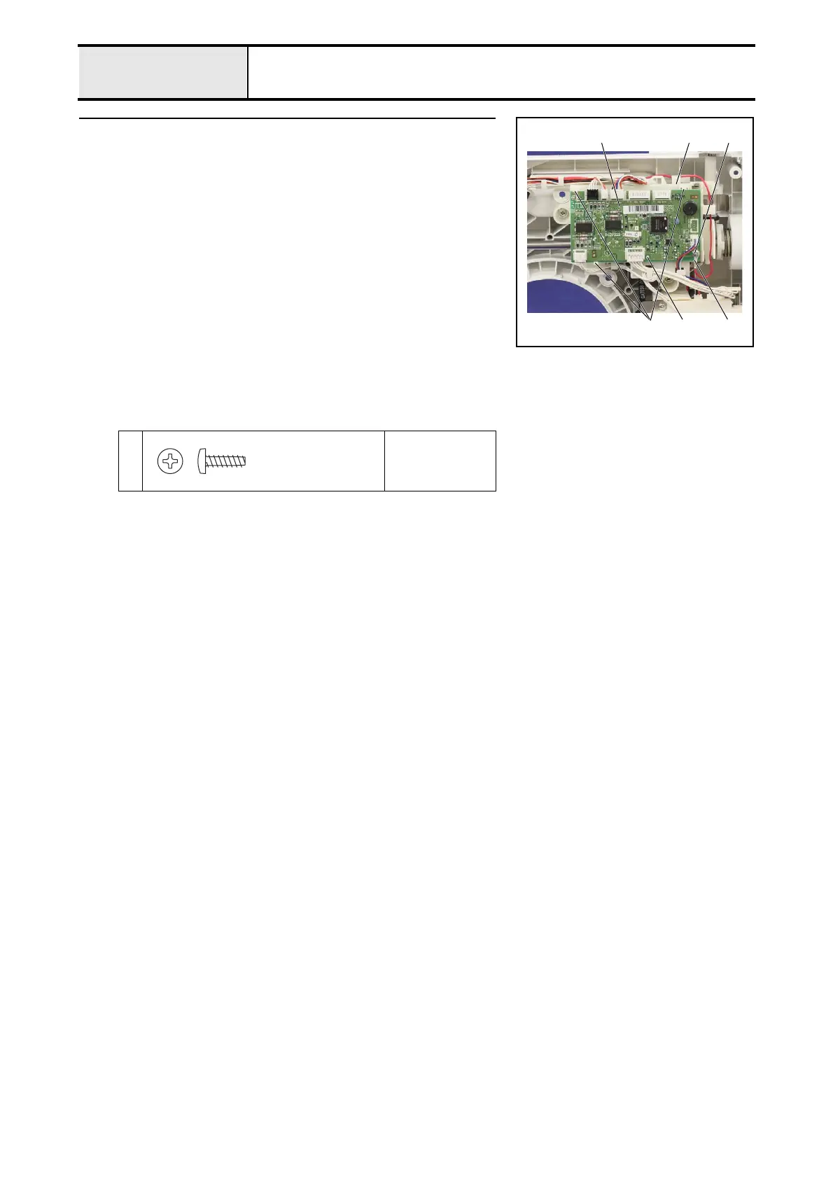
7 Attachment of Main PCB assy
1. Set the main PCB assy. 1 to the shutter cover 2, and then hang on the 3
hooks 3.
*Key point
• Check that the boss of the shutter cover 2 engaged with the
positioning hole of the main PCB assy. 1. (A)
2. Hang the each lead wire on the guide part of the shutter cover 2, and then
connect the each connector to the main PCB assy 1.
*Key point
• Refer to "Special Instructions of Wiring".
3. Secure the lead wire assy: ground 4 and the main PCB assy. 1 to the
shutter cover 2 with the screw 1.
*Key point
• Refer to "Special Instructions of Wiring".
• Check that the bobbin winder switch of the back side of the
main PCB assy. moves surely when the bobbin winder is
switched.
1
Torque
0.39 – 0.78 N·m
3
1
4
1 2
(A)
Taptite, Bind B
M3X10
 Loading...