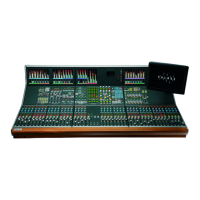
Calrec meters
The parameters below allow the user to
set the operating levels of Calrec meters.
The settings do not affect external
meters, or internal meters which are not
manufactured by Calrec, such as DK and
RTW.
Calrec bargraphs have individual
segments permanently illuminated yellow,
to show the customer’s line up and peak
levels. Below the user can select which
scales will be available to the mixer
operator in the PC Main application. The
user can also set which meter scale will
be the default in the PC Main application.
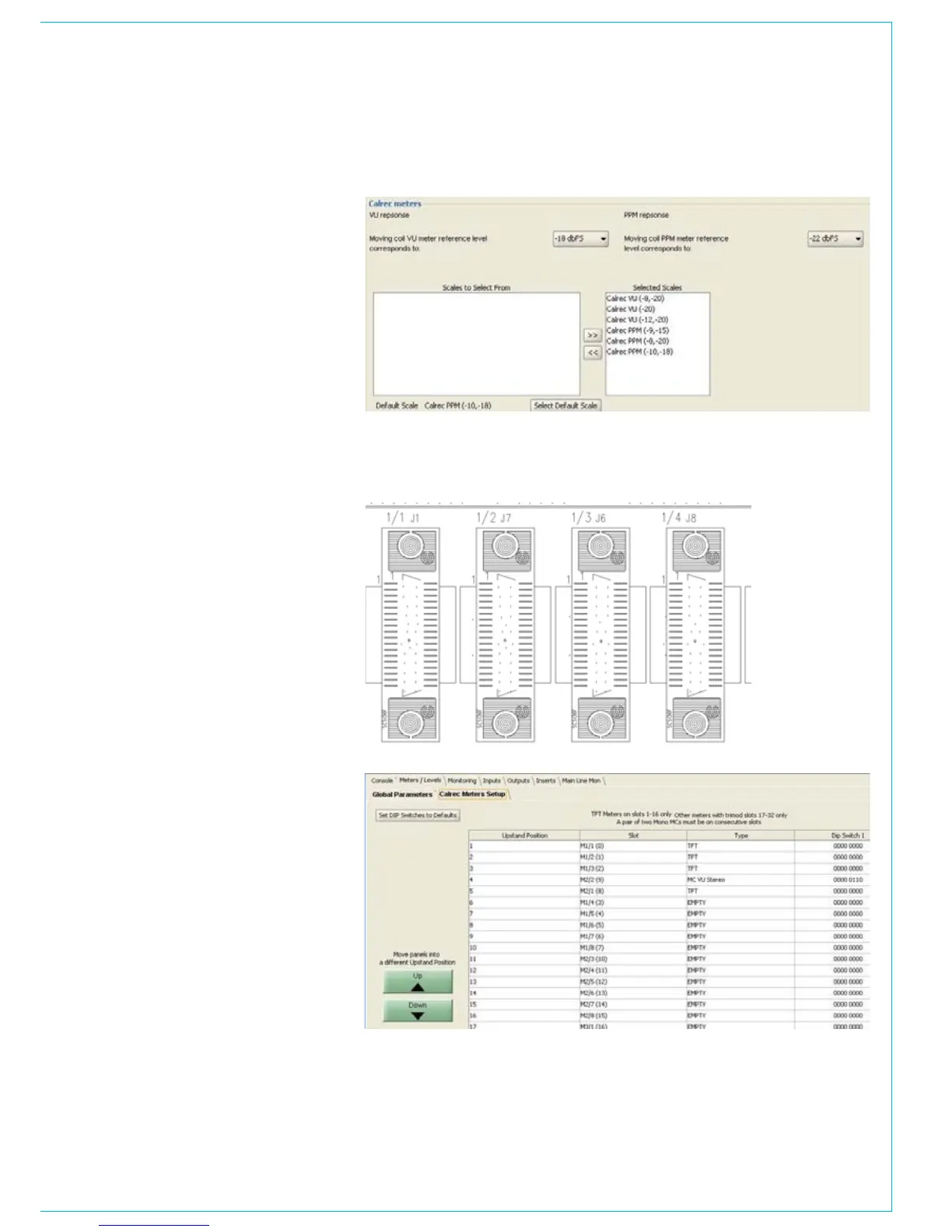
Calrec meter setup
Calrec meters are connected to the meter
mothercard. On the meter mothercard, the
connectors are labelled, see picture to the
right.
The connector numbering, e.g., 1/3,
correlates to M1/3 in the ‘slot’ column
of meter setup page below. The type of
meter fitted in each connector can be
selected using a pull down box, in the
‘type’ column.
All Calrec meters except TFT meters
are fitted will an 8 way DIL switch. The 8
way DIL switch allows the address of the
meter to be set. The address set on the
switches must match the address in the
‘DIP switch 1 column’.
When a new mixer is delivered all the
metering setup is pre-configured.