CALREC Putting Sound in the Picture 55
Auxiliary busses are pre-set to be mono or
stereo on the USER-BUSSES screen.
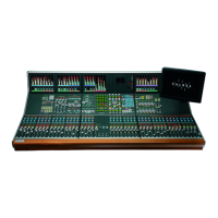
The displays above each rotary control show
what is being controlled (e.g O/P or DIR)
until they are adjusted, when the level is then
displayed. A short time after the adjustment
has been made, the display will show the
label again.
The buttons at the bottom of the Auxiliaries
section influence the function of the
controls.
Auxiliary Feeds
When AUX is selected, these
controls adjust the feeds from
the channels or groups to the
auxiliary output busses.
The ON button switches the feed from
the currently assigned channel or group
to that auxiliary output bus. Each feed can
be pre or post the channel or group fader,
selectable using the PRE button.
If, for example, aux 10 is stereo, then aux
20 will not be available (and aux 20 will not
work on the monitor selector). On mono
auxiliaries, buttons 11 to 20 switch the
control to that numbered aux send. The
Pan button will be inoperative.
PAN makes the control into a Pan control
(balance on Stereo channels). Any pan
offset will be shown as an offset between
the two bars of the display.
Aux Direct Inputs
When DIRECT is selected, this
section controls the Aux Direct
Inputs. The Pre Fader and Pan
controls will be in-operative.
Auxiliary Outputs
When MASTER is selected
these controls adjust the
auxiliary outputs. The ON
buttons switch the output on
and off.
On stereo auxiliaries a dual level display
will be shown, For example, aux 5 and 10.
Here, buttons 15 and 20 will be disabled.
ON
PEAKPEAK
ON
MAIN O/PS
DYN
PRE
DYN
PRE
5.1
MAIN 1
STEREO
MAIN 2
MAIN FADERS
SS
ST
SS
ST
SS
ST
SS
ST
T T
M2
M1
M2
M1
M1
E
C
8
12
16
20
24
4
48
E
C
8
12
16
20
24
4
48
PFLPFL
ON
20
10
20
ON
PAN
AFL
FDR
PRE
- 6
ON ON ON
AUXILIARIES
16
6
17
7
18
8
19
9
+ 3.5 6 -12.0 7 + 1.0 8 -18.0 9
15
5
-10
11
1
12
2
13
3
14
4
+ 3.% 1 -12.0 2 + 1.0 3 -18.0 4
AM5589
DELAY
<< >>
37/25680.0 ms
RESOURCE USED
TONETONE
70
60
50
40
30
20
15
10
0
5
70
60
50
40
30
20
15
10
0
5
DYNDYN
EXT
5 6
1
EXT
MAIN
2
MAIN
MASTER
2
MASTER
S1 S2
EXT
1 2
3
EXT
EXT
4
EXT
PRESEL
2
INTER
LOCK
MASTER
DIRECT
AUX
DELAY
O/P
INTER
ASS
TALKBACK
DELAY
S1
M1 M2
S2
S1 S2
M1 M2
2.73s
I/P
+2.73s
I/P
RET
INS
SEND
INS
IN
8
8
19
PAN
AFL
FDR
PRE
18
PAN
AFL
FDR
PRE
17
PAN
AFL
FDR
PRE
16
PAN
AFL
FDR
PRE
ON
15
ON
PAN
AFL
FDR
PRE
ON ON ON
14
PAN
AFL
FDR
PRE
13
PAN
AFL
FDR
PRE
12
PAN
AFL
FDR
PRE
11
PAN
AFL
FDR
PRE
AUxILIARIES
There cannot be a level offset on the
output display.
LOCK
Lock will lock the panel into
output mode. If LOCK is not
selected, the panel reverts to
Aux if a fader assign button is
pressed.
Interrogate Mode
INTER (latching) puts the panel
into Interrogate mode. If the Aux
ON buttons are held down, the
fader assign buttons of all the
paths feeding that buss will remain lit. The
fader assign buttons of paths which are not
feeding the buss will cease to be lit.
Paths can be added or removed from the
bus under interrogation, by selecting or de-
selecting their fader assign buttons.
If you are using Style 1 faders, then the
way in which the fader assign buttons
light is slightly different. Please refer to
Appendix A at the end of this manual.
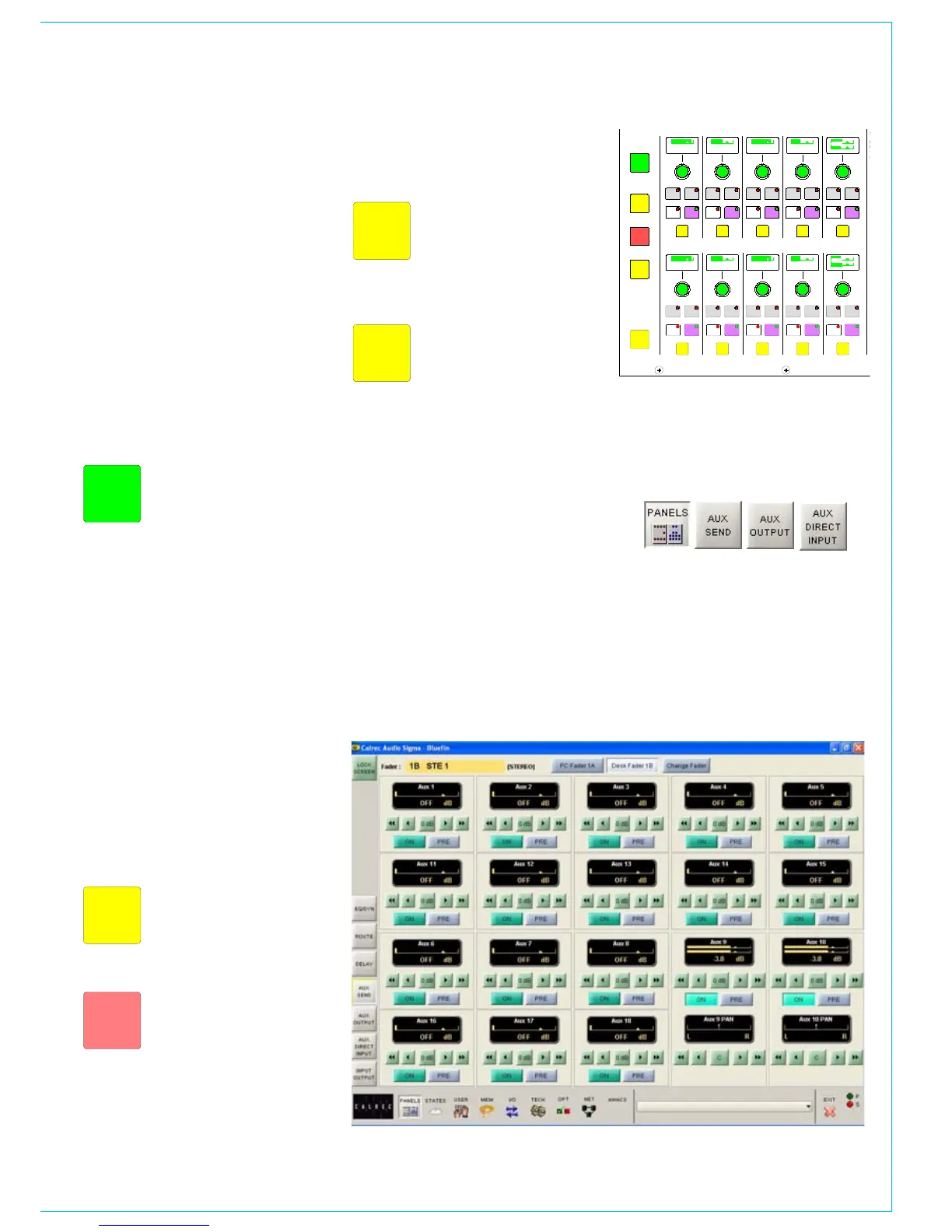
Panels - Auxiliary Control Screens
The user can view and adjust the auxiliary
send, auxiliary output and auxiliary direct
input controls using the Panels - Aux Send,
Panels - Aux Output and Panels - Aux
Direct Input screens.
All of the auxiliary controls available on
the control surface are available on the
screens.
In addition, the user can choose whether
to adjust the Aux send and output settings
of the currently assigned fader path, or
to select a different fader, known as the
“PC Fader” to which aux send and output
settings can be applied independently of
the current assignment.