Do you have a question about the Calrec SIGMA and is the answer not in the manual?
Console modifications and their impact on warranty and features. Validates EMC and safety.
Procedures for handling static-sensitive parts to prevent damage and protect warranty.
Describes symbols indicating electrical hazards and the need for documentation reference.
Notes on not removing power supply blanking plates due to risk of electric shock.
Contact details and services for technical assistance and after-sales support.
Information on Calrec's commitment to high standards and customer feedback.
Describes the Bluefin High Density Processing System and its benefits like resilience and HD capability.
Highlights Calrec's customer value, world-wide base, and product reliability over 20 years.
Details the capabilities of channels and groups, including EQ, filters, dynamics, and routing.
Describes the main, sub-main, and auxiliary busses, including their EQ, filters, and routing options.
Outlines system features like fader count, touch sensitivity, surround capabilities, and I/O options.
Explains the console's independent DSP operation, fast boot times, and hot-swappable components for reliability.
Specifies supported formats, interface types, sample rate conversion, and noise performance.
Details analog input conversion, impedance, sensitivity, noise, distortion, and CMR.
Specifies analog output conversion, impedance, distortion, and frequency response.
Lists operating and non-operating temperature, humidity, and altitude specifications.
Explains how faders control independent A and B audio paths, with color indication for active paths.
Describes how Assign buttons link faders to central control panels for settings access.
Defines paths as channels/groups/mains and ports as inputs/outputs, connected via a matrix.
Explains how ports are grouped into lists for easier selection and management.
Illustrates the system's card configuration and I/O expansion capabilities.
Describes how options settings are saved and loaded separately from memories, affecting console behavior.
Details the use of a second PC screen for extended desktop functionality with specific screens.
Refers to Appendix A for specific button layout and assignment indications for Style 1 faders.
Explains how each fader controls two independent A and B audio paths.
Describes the CUT button's function, equivalent to fading out, and the availability of ON buttons for channels/groups.
Explains the two user-definable rotary controls per fader for assigning almost any control.
Details talkback availability to direct outputs, subject to On-Air inhibits.
Explains how ALL A and ALL B buttons switch channel faders to display either A or B path.
Describes how VCA masters can be nested, affecting slaves of slaves.
Explains how VCA group settings affect surround master spill legs.
Details how holding an assign button indicates VCA group members and their status.
Describes assigning auto-faders to opto inputs using the Options-GPI screen.
Explains the User-Auto Fade screen for assigning auto-faders to channel or group faders.
Details adjustable fade in and out times for auto-faders, ranging from 10ms to 5s.
Explains how auto-fader functions on surround masters affect spill legs.
Describes how to enable layer locking via the Options - Misc screen.
Explains how to choose which layers are locked to specific faders via the User - Layer Locking screen.
Details how to select multiple cells to simultaneously assign layer locks to faders.
Explains how to create a surround channel by assigning a fader as a surround master.
Describes screens for controlling individual legs of surround channels and optional spill panels.
Details how inputs are patched to spill legs, not the surround master channel.
Explains the mic open circuit operation when a surround spill leg is faded up and routed.
Describes how spill paths can be made independent for EQ, filters, and dynamics control.
Provides alternative selection controls for surround channels and their spill paths.
Allows activation of spill path independence and adjustment of fader level via the User-Spill screen.
Explains user dynamic link busses for surround channels and groups, with independent spill leg options.
Describes how alternate EQ and filter settings apply to non-independent spill paths.
Details how VCA group settings affect surround master spill legs, and the impossibility of spill faders being masters/slaves.
Explains independent selection of APFL, tone, and CUT for spill legs, with master control for tone inhibit.
Describes how pre/post selections for inserts, direct outputs, etc., affect all spill legs, with individual adjustment possible.
Details how to assign ports to inputs 1 and 2 for the currently assigned fader.
Explains how to access and manage port lists using Options - Port List screens.
Describes how to select path types (GROUP, SURR, STEREO, MONO) for the assigned fader.
Explains how to move or swap paths and entire fader strips using dedicated buttons.
Details how to clear channel or group paths and their settings using CLR and EXEC.
Describes alternative fader path selection using nudge buttons and A/B buttons.
Explains how to connect ports to channel and group direct outputs, with pre-EQ or pre-fader options.
Describes the pool of assignable inserts for channels, groups, and main outputs.
Covers input selection, phantom power, SRC, and stereo/mono configuration.
Details coarse and fine gain adjustment, linking inputs, and gain range for different input types.
Explains balance control on stereo channels and its function as an input pan or gain trim.
Describes pre-fader width control on stereo channels and groups, from mono to wide.
Explains how assignable inserts are patched in and out of channel paths.
Covers panning for stereo and surround signals, allowing simultaneous panning to stereo groups.
Provides a schematic illustrating channel input, insert, dynamics, and output routing.
Describes the front signal panning from left to right and its use as a balance control on stereo.
Explains panning the signal between front and back, with separate rear level control.
Details the rear signal panning from Left Surround to Right Surround.
Explains controlling LFE level independently and adjusting surround legs for 5.0 level.
Describes the divergence control for mono channels and stereo contributions to surround paths.
Explains the C ONLY button for connecting channel output to the centre bus.
Explains that joystick controls require CONTROLS ACTIVE to be selected for effect.
Describes how the freeze function stops a joystick axis from altering audio.
Explains the disengage function, protecting against accidental changes.
Details how the snap to audio button causes the joystick to position to the audio.
Explains how to assign and adjust delay values for channels, groups, and inserts.
Describes delay assignment for surround channels, linked to the surround master.
Details delay available in insert send/return paths for extra delay.
Explains how to interrogate channels with delay assigned using the interrogate button.
Describes the delay controls available on the screen.
Explains display unit options for delay, affecting nudge buttons.
Describes assigning delay controls to Wild controls for adjustment.
Explains how to clear paths and their settings using CLEAR PATH and EXEC.
Details moving paths or entire fader strips, including Wild Control assignments.
Describes choosing between full surround or stereo downmix for surround direct outputs.
Explains how to set the function of the fader bargraph using I/P, DIR O/P, DYN, and OFF buttons.
Details assigning rotary controls to Wild controls and the "FLIP" function.
Explains assigning controls to multiple fader paths or regions.
Lists filter specifications for LF and HF, including Q and frequency ranges.
Describes the ALT EQ FLTR button for switching between two EQ and filter control sets.
Explains how the EQ FLAT button clears all EQ settings to flat.
Describes the screen for viewing and manipulating EQ and filter response curves.
Details gate threshold, recovery, depth, attack, and make-up gain settings.
Lists compressor settings including threshold, recovery, ratio, attack, and sidechain listen.
Details expander settings like threshold, recovery, depth, attack, and ratio.
Explains linking dynamics of multiple channels to one of two link busses.
Describes the screen for viewing and manipulating dynamic response curves.
Details what settings are copied for I/Ps, EQ, FLTR, DYN, PAN, FDR, RTG, AUX, and WILDS.
Explains how settings are copied between surround, stereo, and mono channels.
Describes system modes (Transmit, Rehearse, Neither) controlled via buttons or GPI.
Explains how ENABLE and CONSOLE RESET affect only the Control System, ensuring audio continuity.
Details PSU monitoring, hot spare takeover, and PSU FAIL indicator functionality.
Clears assigned channel settings except port assignment.
Recalls the default console setup configuration, replacing all settings.
Activates Replay mode, switching selected channels to input 2, with selections stored with user memories.
Explains how to make or remove routes to tracks, groups, or main outputs using numbered buttons.
Details control of track output to multi-track, including IFB or general purpose bus usage.
Describes how to discover fader paths feeding routing busses by entering "Interrogate" mode.
Explains track level control and assignment to channel 'wild' controls.
Provides alternative controls for routing, allowing selection of assigned or PC fader paths.
Allows control of track output levels using virtual faders and a master fader.
Explains how to route channels and surround spill paths to mains, groups, tracks, and auxiliaries using a selection table.
Details how main outputs can be pre-set to surround or stereo, including downmix options.
Allows setting main and sub-main outputs to stereo or surround.
Enables selection of group busses as mono, stereo, or 5.1 surround.
Explains pairing mono auxiliary busses to create stereo auxes.
Describes controls for adjusting feeds from channels/groups to auxiliary output busses, including PRE/ON buttons.
Details controls for Aux Direct Inputs, noting that Pre Fader and Pan are inoperative.
Explains MASTER control for auxiliary outputs, including ON buttons.
Details talkback availability to auxes, main/sub-main outputs, external sources, tracks, and studio.
Explains how to adjust tone frequency using nudge buttons or the sweep function.
Details how to adjust test tone level using nudge buttons or the REF LEV button.
Describes the use of Tone Interrupt buttons for testing stereo monitoring and metering.
Explains how external input buttons replace tone with mono, stereo, or 5.1 surround sources.
Explains the display of Live and Selected Memories, and how changes affect the console.
Details how to enter memory numbers or select from Flash ROM lists to choose the Selected Memory.
Describes how to save console settings to the Selected Memory or a specific memory number.
Explains how the Preview button displays Selected Memory settings without changing current settings.
Describes arranging memories into a pre-set list (stack) for easy access during a show.
Details backing up, restoring, renaming, and clearing memories from Flash ROM.
Explains how to save and restore stacks as sessions.
Explains how port connections can be isolated from memory recall, preventing overwrites.
Notes that surround masters can be isolated, but spill paths cannot.
Describes how to select specific channels or components for partial memory saves.
Explains how monitor sources are grouped into user-definable banks for selection.
Details the 16 selection buttons for choosing monitor sources or functions within a bank.
Describes six miscellaneous loudspeaker outputs for assigning monitor sources.
Explains the four buttons for presetting monitor sources for immediate listening.
Details the level controls for main and small loudspeakers and the changeover button.
Explains how to control installed decoders and access their remote functions.
Describes allocating monitor sources to banks of selection buttons for the monitor panel.
Details saving monitor configurations to PC and loading them into the desk.
Allows choosing a previously saved monitor configuration file.
Saves the current configuration to a file without loading it onto the console.
Retrieves current console settings and displays them on the screens.
Emphasizes saving options to disk and flash for monitor configurations.
Explains options for mute, cut, dim, and mono/stereo monitoring for misc outputs.
Describes Tone and M/S selection for meters 1-4.
Details available listening modes (mono, stereo, surround) and their selections.
Describes PFL override options, PFL to MON, PFL CLEAR, and APFL Flash.
Provides setup notes for Dolby decoders, including alternate modes and output options.
Allows selection of top, middle, and bottom colours for meter bars, independently.
Enables shuffling of surround signal order for meter display.
Details individual and global adjustment of TFT screen brightness.
Explains how to set the number of rows and meter height within columns on TFT screens.
Details the number of columns (4 or 6) and their widths per row on TFT screens.
Describes how to set meter height within a column to occupy one, two, or three rows.
Allows selection of meter scales (PPM, VU, Phase) individually or globally.
Resets all meter positions and clears all settings on the upstand.
Explains displaying two tracks per meter position and column width effects.
Details saving meter configurations to PC and loading them into the desk.
Allows choosing a previously saved meter configuration file.
Saves the current configuration to a file without loading it onto the console.
Retrieves current console settings and displays them on the screens.
Emphasizes saving options to disk and flash for meter configurations.
Explains how available ports are grouped into lists for display and patching.
Details viewing options for sources as pairs, individual, or with diagnostic information.
Describes buttons that select console path types for input ports.
Explains choosing which set of faders are available on the screen.
Details assignment process by selecting source, input/output, and patching.
Explains isolating port connections from memory recall to prevent overwrites.
Describes gaining control (ownership) of networked Hydra sources/destinations.
Explains grouping available ports into lists for patching buss outputs.
Details viewing options for ports as pairs, individual, or with diagnostic information.
Describes buttons that select categories of console output signals for patching.
Details assigning output signals to output ports and removing patches.
Explains how to remove an output signal from its port assignment.
Explains isolating port connections from memory recall.
Describes a system to protect critical port configurations from accidental removal.
Details patching for the LS monitor insert send and return ports.
Explains how to patch output ports for direct outputs.
Describes patching output ports for external meters like DK phase scopes.
Details patching input ports directly to output ports.
Explains patching input ports directly to direct inputs.
Describes viewing input ports by list and accessing longer descriptions.
Explains that lists are set up using the Options - Port List screens.
Details adding ports to lists or creating new lists using the Port Name column.
Explains creating, deleting, and modifying lists using dedicated buttons.
Describes using control surface port selection to access lists, showing current port and its list.
Explains giving ports long descriptions for use in patching and usage screens.
Details allocating Hydra ports to lists and their association with network configurations.
Explains grouping ports within a list into sets, with options to create, add, or remove sets.
Details saving list configurations to PC and loading them into the console.
Allows choosing a previously saved list configuration file.
Saves the current configuration to a file without loading it onto the console.
Retrieves current control surface settings for display and modification.
Allows opening list configurations that use the current network configuration.
Clears the current list configuration of all settings.
Emphasizes saving options to disk and flash for list configurations.
Describes displaying system information and saving the default memory.
Allows setting the headroom available above input gain up to the channel fader.
Explains enabling/disabling the use of rotary control switches to set default values.
Describes how holding a fader in PFL overpress mode activates the channel on assign panels.
Explains using push switches on Wild controls to set default values or control ON/OFF status.
Enables Layer Locking, preventing A/B layer changes via ALL A/B buttons.
Disables A/B layer switches on faders, with flashing if a locked button is pressed.
Sets functionality for short presses of All A/All B buttons, with long press switching fader display permanently.
Explains how to assign available sync sources to priority slots.
Allows resetting the system to the first source after a failure, when it becomes available.
Explains how Talkback and tone input ports are selected from lists.
Details assigning sources to inputs and selecting Patch.
Covers controls for analog gain, phantom power, and SRC switching.
Disables VCA group changes to prevent accidental modifications.
Allows linking or separate adjustment of gains for channel inputs 1 and 2.
Enables scrolling to the fader in the patching list when a fader assign button is selected.
Sets Move Path buttons to move selected paths or entire fader strips.
Allows control of switcher functions via Ross Synergy system.
Explains assigning functions or outputs and moving/removing assignments.
Details setting relays to latch or pulse on activation/deactivation.
Allows verification of connected device operation via the Test button.
Assigns general purpose inputs to console functions, channels, or Auto Faders.
Details allocating functions and Hub ID numbers for serial interface ports.
Explains using USB connectors for external modems for remote console access.
Details connecting the mixer PC to a user's LAN for network access.
Lists default usernames and passwords for PC access and configuration.
Lists commercially available hardware for building networks, requiring proprietary interface hardware.
Describes screens for configuring Hydra I/O boxes, editing networks, and status representation.
Explains console synchronization using network packets from Hydra.
Advises keeping the network private for deterministic performance, excluding other data.
Describes using console racks for connections to routers, monitoring, etc., not networked to other consoles.
Details the indicative LEDs visible on the front panel for PSU status, fan, and port connection/activity.
Explains frequency synchronization using packets from the Hydra network.
Describes support for remote firmware/software updates and diagnostics via Ethernet/RS232.
Explains how devices are identified by unique IP addresses, with examples.
Recommends against combining modular and fixed Hydra I/O ports for 5.1 surround signals.
Lists available unit variants for fixed format boxes, including mic/line and AES configurations.
Describes mains power, dual internal PSUs, IEC connectors, and PSU/fan monitoring.
Details front panel indicative LEDs for PSU status, fan, port connection, and signal presence.
Explains frequency synchronization using packets from the Hydra network.
Describes support for remote firmware/software updates and diagnostics.
Recommends against combining modular and fixed Hydra I/O ports for 5.1 surround signals.
Details optional Dolby E decoder modules and the required patching for them.
Provides dimensions and weights for SDI de-embedder units.
Describes the modular design with 14 slots for various modules like input, output, and PSU.
Explains the function of ground lift switches on input/output modules.
Details the process of removing modules for service using an extraction hole.
Notes that external connections are on the front face, requiring space for cables.
Describes mounting the modular Hydra I/O box using side angle brackets.
Explains the location and control of cooling fans in the rear of the unit.
Details the external earth stud on the rear for connection to an external earthing system.
Provides instructions for mounting the power supply rack horizontally using side and rear brackets.
Explains the fan cooling system and required clearance for airflow.
Details saving network configurations to PC for later recall.
Notes that network configurations are not saved with user memories and require separate saving.
Explains allocating Hydra input/output ports to lists, linked to network configurations.
Recommends against combining modular and standard Hydra I/O ports for 5.1 surround signals.
Describes gaining control of networked Hydra ports, overriding ownership via grab buttons.
Details optional Dolby E decoder modules and the required patching for them.
Provides dimensions and weights for SDI de-embedder units.
Warns that setup changes are not adopted until programmed into processors, requiring the programming utility.
Allows adjustment of PFL, Track AFL, and Direct Output AFL functions (momentary, latching, auto).
Explains how to set the location of the assigned fader panel for operator access.
Describes clearing auxiliary settings and defining the aux clear function.
Explains using a card reader's memory card for automatic user file backup.
Details connecting the mixer PC to a LAN and distributing AWACS messages.
Allows setting mixer operating levels for analogue (dBu) and digital (dBFS) audio.
Details parameters for setting Calrec meter operating levels and scales.
Explains connecting Calrec meters to the mothercard and setting DIP switch addresses.
Allows setting loudspeaker output formats (stereo, surround) and phantom centre options.
Describes six miscellaneous loudspeaker outputs and their muting/labeling functionality.
Explains how to label and display assigned monitoring system meter selectors.
Covers labeling input ports, configuring them as stereo/mono, and saving setup files.
Explains that output ports can be adjusted similarly to input ports.
Explains configuring insert ports like input/output ports and grouping them into lists.
Details programming control surface processors, including kernel mode and file transfer.
Explains programming rack processors, entering kernel mode, and verifying software.
Provides steps to force a processor into kernel mode if repeated attempts fail.
Explains creating the editor installer application on the console PC.
Describes how bundles contain specific desk details for the Offline Editor.
Advises devising a logical structure for managing file bundles for various consoles.
Details unpacking the installer, locating the executable, and installing the application.
Explains starting the offline editor, importing bundles, and running the frontend.
Describes saving completed changes into a bundle for loading back into the console.
Explains how to find and select memories from a bundle to load into the console.
Details loading various file types and using the MEMORY/SETUP screen to restore memories.
Explains how each fader controls two independent A and B audio paths.
Describes how assign buttons link faders to central control panels.
Details how labels are associated with input or group numbers, with display in green/amber.
Explains the CUT button and the availability of ON buttons for channels/groups.
Describes PFL provision on fader overpress and buttons, heard on small/main LS.
Explains how holding an assign button indicates VCA group members.
Describes entering "Interrogate" mode to discover fader paths feeding routing busses.
Explains using Monitor and Meter Selectors to choose sources and display information.
Describes allocating monitor sources to user-definable buttons via Options-Mon I/P & TB screen.
Details the SMALL LS level control and the "change over" button.
Explains listening modes like NORMAL, ØR, L+R to L, and MONO.
Describes AFL feeding Control Room LS outputs and PFL availability on Selector 2.
Details control of selected decoders via buttons for output modes and compression.
Explains the main and ancillary meters, their configurations, and tone switching.
Notes the availability of a portrait style monitor selector and LS panel.
Allows switching the LS monitor insert in and out, with send/return ports patched separately.
Details PFL to MON/HP options and APFL Flash enable/disable functionality.
Lists new features like PC front end application, Aux Bird Beater, and MADI interface support.
Details Hydra Audio Networking, Grab Feature, and new Front End screens.
Highlights Partial Memories, Automatic Cross Fading, and Wild control push-switch option.
Covers TFT meter panels, Nexus Router support, and gain linking options.
Introduces new style assignable monitor panels and delay features.
Details network redundancy, altered networking screens, and remote mic cut system increase.
Notes System Plus logo changes.
Covers 320 mono channels, spill panel support, routing matrix, and EQ/Dynamics screens.
Mentions support for up to 33 SDI boxes on a network.
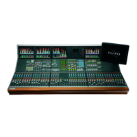
| Brand | Calrec |
|---|---|
| Model | SIGMA |
| Category | Music Equipment |
| Language | English |