The different types of decoder are
located in seperate banks, and functions
are chosen in the same way as monitor
sources.
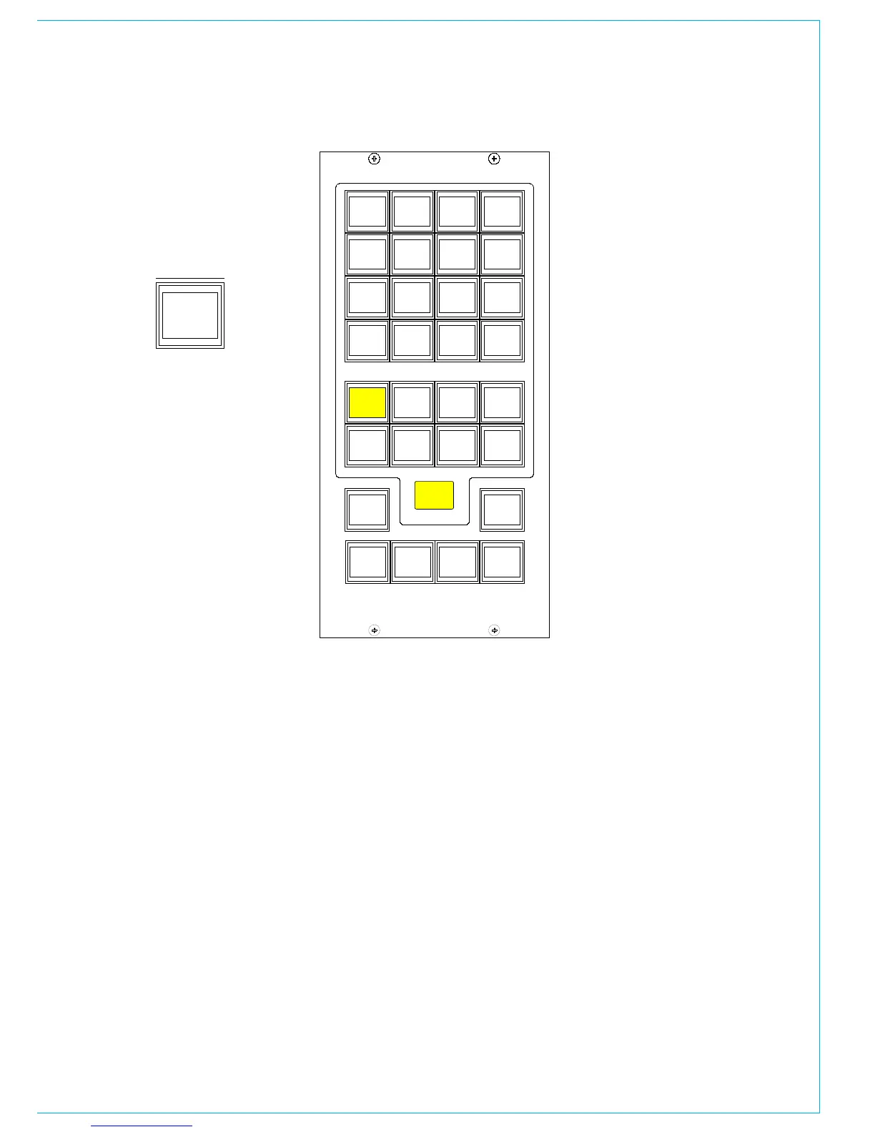
The decoder function buttons are as
follows:
1 button for Pro Logic mode. When using
a Dolby DP570, it is assumed that it will be
set to Dolby Digital mode either in manual
or auto detect mode.
3 buttons for Alternate Compression
Modes: CUSTOM, LINE and RF. If none are
selected, there will be no compression and
no dialogue normalization.
4 buttons for Alternate Output Modes:
PHAN CENTRE, 3 STEREO, STEREO and
MONO. If none are selected, the output will
be full surround.
When controlling a Dolby SDU4, LT/RT
decoder, only the stereo and mono output
mode buttons will function.
dECOdER REMOTES
On the Dolby unit:
<label> means press the button with the
name label.
Power up the unit.
<setup>
<down arrow> until you see “SYSTEM
SETTINGS”
<enter> Unit name is now displayed
<down arrow> until you see “GPI setup”
<enter> “GPI pin 23” is displayed
<enter> “GPI pin 23 trigger” is displayed
<enter>
<down arrow> until you see “Edge”
<enter>
<esc> “GPI pin 23 trigger” is displayed
<down arrow> “GPI pin 23 Polarity” is
displayed
<enter>
<down arrow> until you see “Positive/
High”
<enter>
<esc> “GPI pin 23 Polarity” is displayed
<down arrow> “GPI pin 23 Function” is
displayed
<enter>
<down arrow> until you see “FULL”
meaning surround.
<enter>
<esc> “GPI pin 23 Function” is displayed
<esc> “GPI pin 23” is displayed
<down arrow> “GPI pin 24” is displayed
Repeat the process for all the GPI pins 24
- 31
<esc> “GPI setup” is displayed
<down arrow> “GPO setup” is displayed
Now go though the same routine to set up
the outputs on pins 7 to 14 (as drawing/
spreadsheet) with trigger as “Level”,
Polarity as “Positive/High”, and function as
spreadsheet.
<esc> Until back at original menu.
Note: With issue 1 cable, the outputs are
on pins 8 to 15.