Operations
Canrig Drilling Technology Ltd. 5-1
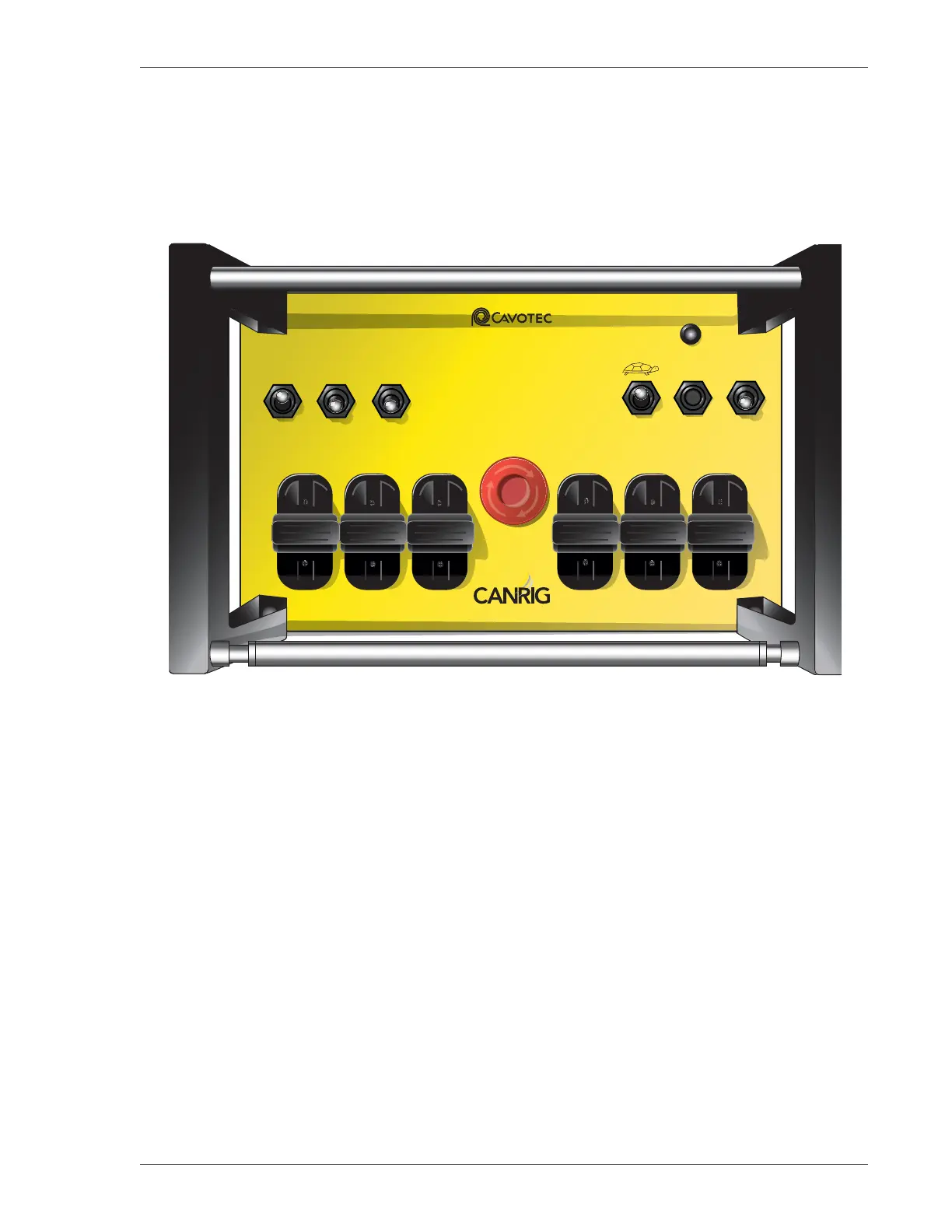
Wireless Terminal
To operate the wireless terminal (Figure 5-1), pull out or twist the E-STOP button and ensure all switches
and joysticks are in the NEUTRAL position. Flip the Terminal ON/OFF switch ON, and press the
TERMINAL START/RESET button to enable radio communication. After an approximately one second
self-test, the terminal will establish contact with the base unit.
Figure 5-1: Wireless Terminal
The Status indicator should display a steady light. If the Status indicator is flashing, an error has occurred.
Refer to the original manufacturer’s instruction manual for troubleshooting procedures.
After successful powerup, use the TERMINAL START/RESET button to enable (arm) the wireless terminal
and to reset any operational errors.
When power is first supplied to the Catwalk, or after power has been interrupted and restored, the PLC
seeks communication with the wireless terminal. The error message “Wireless Radio Controller E-Stop
Pressed” or “Radio Failure” is displayed on the HMI screen until the wireless terminal is turned on and
enabled, or until the Catwalk is switched to Control Console mode.
The wireless terminal Motor START switch is used to start the electric motor of the HPU.
MC 3200 EX
STATUS
ODS
LOCATOR PIN
CARRIER LIFT
ODS
P-RACK
DS
P-RACK
ODS INDEX
ODS KICKER DS KICKER
OUTER
RAISE
INNER
RAISE
Service Tel: +1 866.433.4345
www.canrig.com
INNER
RAISE
FWD.
BACK
DS INDEX
SKATE
MOTOR START RESET
TERMINAL
START
TERMINAL
ON
TERMINAL
OFF
E-STOP
OUTER
RAISE
UP
DOWN
DS
LOCATOR PIN