PC3000 with 26" Deck (PC3000-26) User’s Manual
3-10 Document ID 13-003 v 2.0
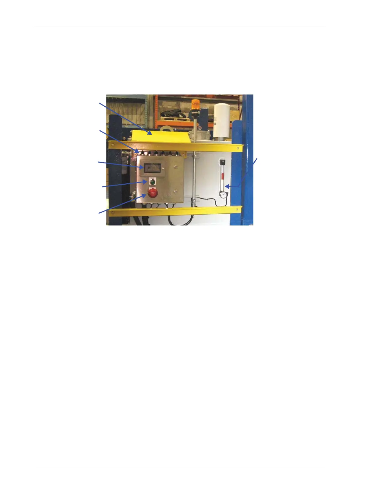
Control Console
The control console (Figure 3-9 through Figure 3-11) is located on the Drillers Side flare end. It consists of
an HMI screen display, hydraulic motor running light, control bank of switches/levers, and various control
buttons on the left and right sides of the console (see “Control Console,” page 5-2.)
Figure 3-9: Control Console
The HMI screen indicates Catwalk status. When an error occurs, an amber strobe light flashes and a
message on the screen describes the error.
A motor running light is illuminated while the electric motor is in operation.
When pressed, the E-STOP button removes power from the electric motor and causes the Catwalk to
cease operation. An error message is displayed on the HMI screen.
The control bank on top of the control console (Figure 3-9 above and Figure 5-2, page 5-3), consists of
switches and levers for operating the Catwalk. (See “Control Console,” page 5-2.)
Protective Cover
HMI Display
Screen
HYD. MOTOR
RUNNING Light
EMERGENCY STOP
(E-STOP) Button
Control Bank of
Switches/Levers
(Larger view on
Figure 5-2, page 5-3)
Tank Oil Level and
Temperature Gauge
(Larger view on
Figure 3-15, page 3-
16.)