3.4.- CONNECTION DIAGRAMS
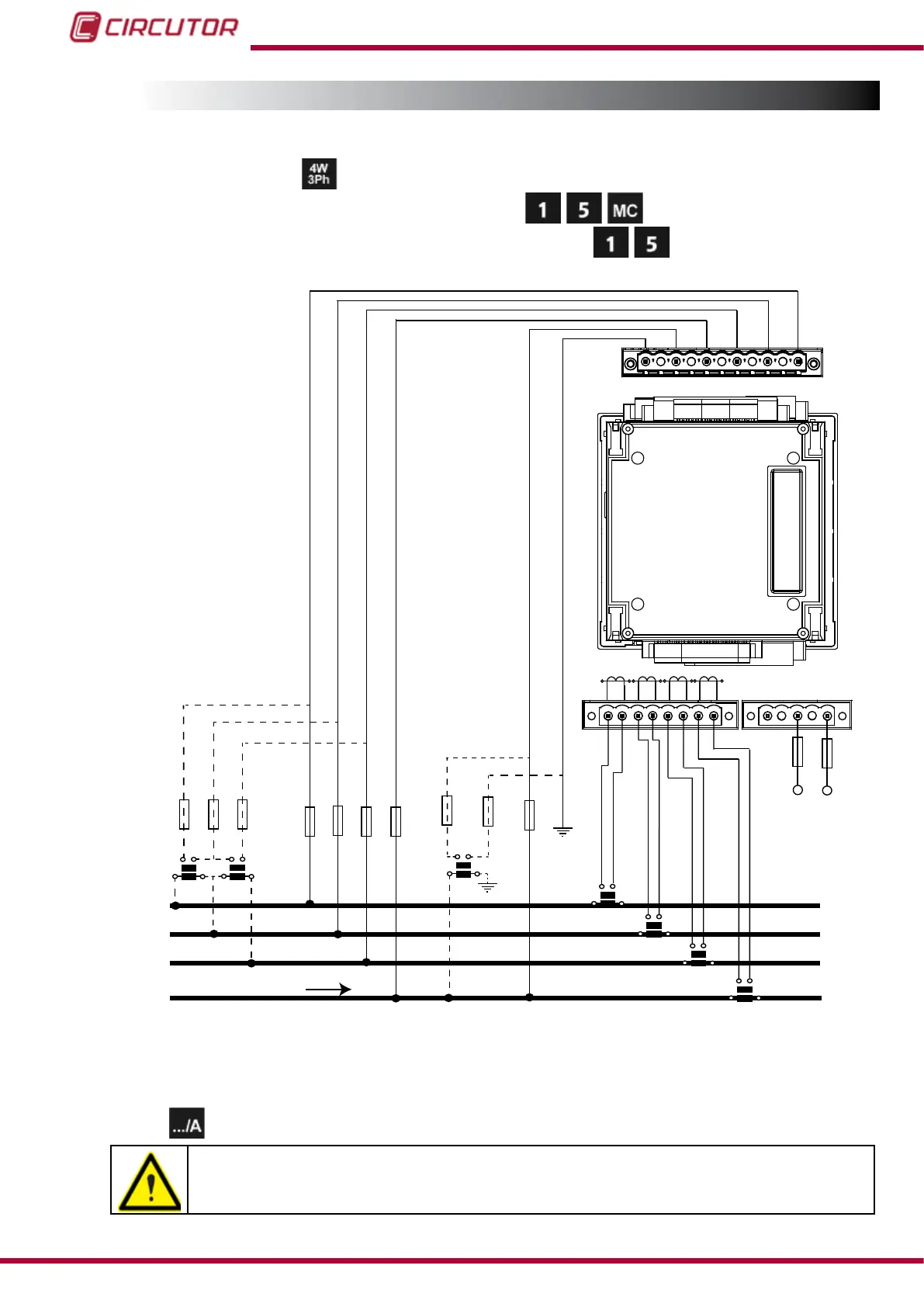
3.4.1.- THREE-PHASE NETWORK MEASUREMENT WITH A 4-WIRE CONNECTION.
Measurement system:
Secondary winding of the current transformer: (MC1 type transformer)
Secondary winding of the neutral current transformer:
Power
Supply
VL1
L1
L2
L3
N V
L3 L2
V
L1
V
VL1 VL2 VL3
a
b
A B
a
b
A
B
S1 S2
S1 S2
S1 S2
L1
P1 P2
L2
L3
P1 P2 P1 P2
S1 S2
LN
P1 P2
NV
REF REF
N
S1
S2
P1
P2
POWER SUPPLY
VL2
VL3 N
VREF
NREF
a
b
A
B
VREF
NREF
S1
S2
P1
P2
S1
S2
P1
P2
S1
S2
P1
P2
LOAD
Figure 3: Three-phase measuring with a 4-wire connection (transformer secondary: /1A, /5A or MC1 (/0.250)).
Note: The unit can calculate the neutral current without having to measure it, option: Calculated
current
.
The MC1 transformer secondary value is set to 0.250 A
The transformer for measuring the LN neutral current cannot be MC type.
14
CVM-B100 - CVM-B150
Instruction Manual