7.10.3.- CONNECTION DIAGRAM
B(-)
A(+)
S
RS-485
POWER SUPPLY
INPUTS
A(+) B(-)
GND
RS485
S1 S2
S1 S2
S1 S2
L1
P1 P2
L2
L3
300V
~
Ph-NPh-Ph
520V
~
NV
L3L2VL1V
P1 P2
P1 P2
I1 I2
OUTPUTS
Rc R2 R1 Tc T2 T1
S0-
S0+ S0+
B(-)
A(+)
S
CVM B-1xx
+
M-CVM-AB-Modbus
TCP (Bridge)
CVM C10
CVM MINI
PC
Ethernet
CVM B-1xx
+
M-CVM-AB-Modbus
TCP (Switch)
Ethernet
CVM B-1xx
+
M-CVM-AB-Modbus
TCP (Switch)
Ethernet
Ethernet
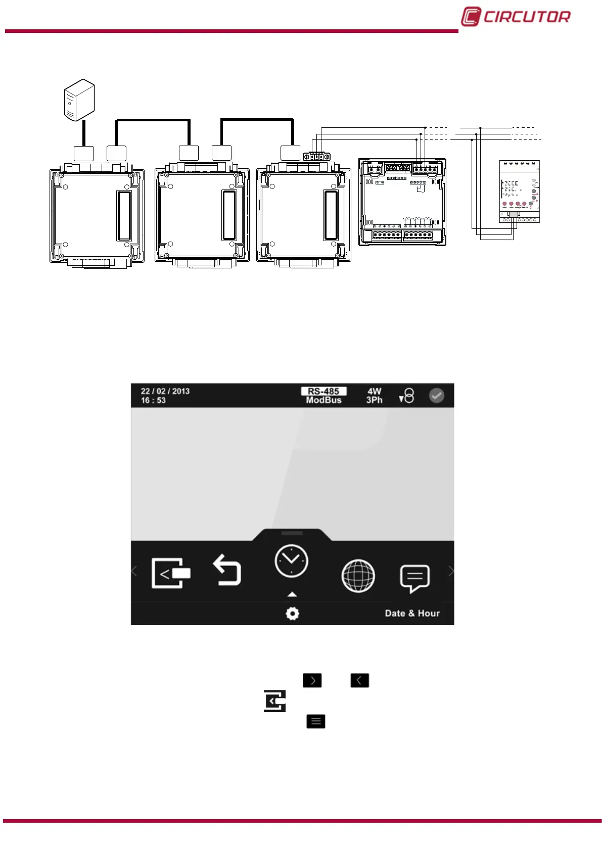
Figure 215:Modbus TCP (Switch) connection diagram.
7.10.4.- CONFIGURATION
You can access the setup menu on the main screen,
Figure 25.
The screen in Figure 216, is the home screen of the setup menu.
Figure 216: Main screen of setup menu.
All the possible programming parameters for the unit appear in the lower area. To congure the
expansion modules you need to, using the keys
and , browse the various parameters
until nding the expansion modules icon, .
To access the selected parameter, press the key
.
If no key is pressed for 5 minutes, the display screen changes automatically to the default
screen.
The main screen of the expansion modules is shown in Figure 217.
305
Instruction Manual
CVM-B100 - CVM-B150