7.2.- RELAY DIGITAL INPUTS/OUTPUTS
This expansion module features 8 relay digital inputs and 8 relay digital outputs.
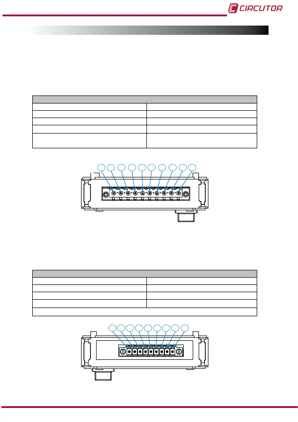
7.2.1.- CONNECTION TERMINALS
A.- Terminals on the upper face
Table 66: List of terminals on the upper face, Relay digital inputs/outputs module.
Unit terminals
1: R
1
, Digital output of relay 1 6: R
5
, Digital output of relay 5
2: R
2
, Digital output of relay 2 7: R
6
, Digital output of relay 6
3: R
3
, Digital output of relay 3 8: R
7
, Digital output of relay 7
4: R
4
, Digital output of relay 4
9: R
8
, Digital output of relay 8
5: COM
, Common digital outputs of relay R
1,
R
2,
R
3
and
R
4
10: COM, Common digital outputs of relay R
5,
R
6,
R
7 and
R
8
1 2
3
4 5 6 7 8 9 10
Figure 150: Terminals of Relay Digital Inputs/Outputs, upper face.
B.- Terminals on the lower face
Table 67: List of terminals on the lower face, Relay digital inputs/outputs module.
Unit terminals
11: COM, for digital inputs 16: I
5
, Digital input 5
12: I
1
, Digital input 1 17: I
6
, Digital input 6
13: I
2
, Digital input 2 18: I
7
, Digital input 7
14: I
3
, Digital input 3
19: I
8
, Digital input 8
15: I
4
,
Digital input 4
11 12 13 14 15 16 17 18 19
Figure 151:Terminals of Relay Digital Inputs/Outputs, lower face.
213
Instruction Manual
CVM-B100 - CVM-B150