7.3.4.- COMUNICACIONES MODBUS
The address of the Modbus memory map depends on the position of the expansion module in
the unit.
Slot 1 will be the position of the expansion module installed just behind the standard unit, and
Slot 2 the next position...
As the maximum number of expansion modules that can be connected to the unit is 4, there
will only be 4 slots.
7.3.4.1. - Programming of transistor digital outputs
The following functions are implemented for these variables:
Function 0x04: reading registers.
Function 0x10: Writing multiple registers.
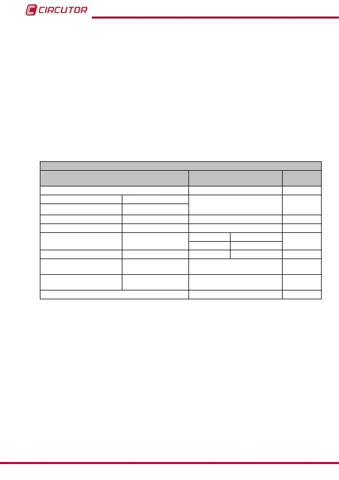
Table 85: Modbus memory map: Transistor digital outputs, expansion modules (Table 1).
Conguration of Transistor Digital Outputs
Configuration variable
Valid data window Default
value
Variable code Table 21 0
Alarm Impulse output
0 to 100% 0
Pre-alarm value -
Minimum value
(1) -
Table 44 0
Maximum value
(1)
Energy meter factor Table 44 0
Connection delay (ON) High period
(2)
Alarm Impulse output
0
0 to 999 s. 1 to 65536
Disconnection delay (OFF)
Low period
(2)
0 to 999 s. 1 to 65536 0
Latch -
0 : Unlocked
1: Locked
0
Output status -
0 : Normally open
1: Normally closed
0
Module no.
0
0
(1)
When programming the maximum and minimum values, the decimals for the variable selected must be included.
(2)
The programmed value is a multiple of 10 ms, when programming 1 the impulse will be at its minimum value of
10 ms.
232
CVM-B100 - CVM-B150
Instruction Manual