Example: Alarm M0_S3 act with latch
M0, Indicates the module where the alarm was activated:
M0, is an alarm triggered in the unit.
M1 ...M4, is an alarm in the expansion module 1...4.
S3, Indicates the module output that has activated the alarm.
In the event of alarms installed in the unit, M0:
- S1, is the digital output of transistor 1.
- S2, is the digital output of transistor 2.
- S3, is the digital output of relay 1.
- S4, is the digital output of relay 2.
Date : Date of the alarm.
Hour: Time of the alarm.
The alarm log can be deleted on the Parameter reset screen of the setup menu ( “5.6.19 Pa-
rameter reset.”)
If no button is pressed for 5 minutes, the display screen changes automatically to the default
screen, which displays the voltage measurement of 4 parameters.
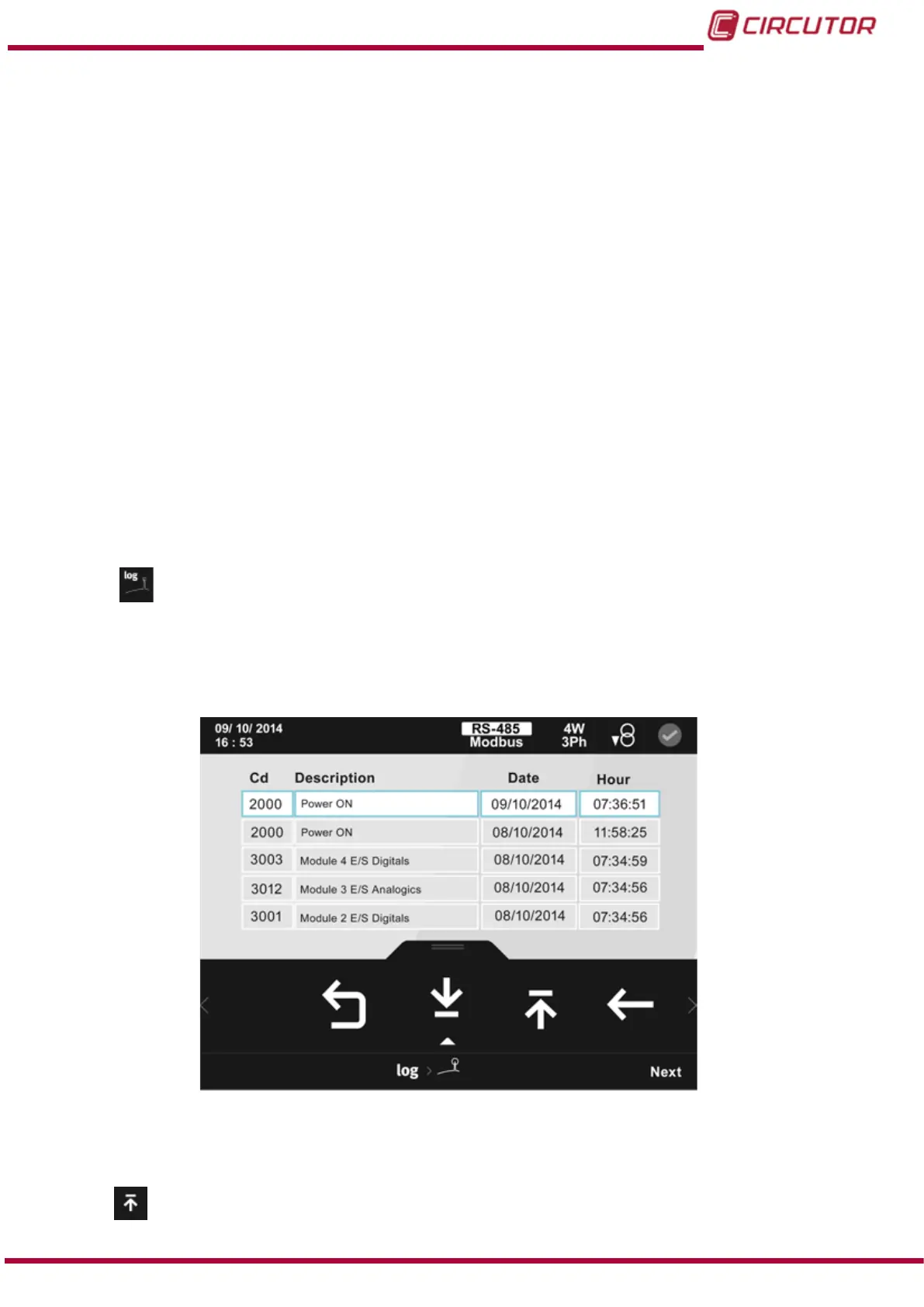
5.4.2.-
EVENT LOG
This screen shows the log of the last 50 events occurring in the unit and the installed expansion
modules, including a brief description and the date and time of the event.
Figure 94:Event log.
The lower area menu options are:
Previous, scrolls up the event log.
109
Instruction Manual
CVM-B100 - CVM-B150