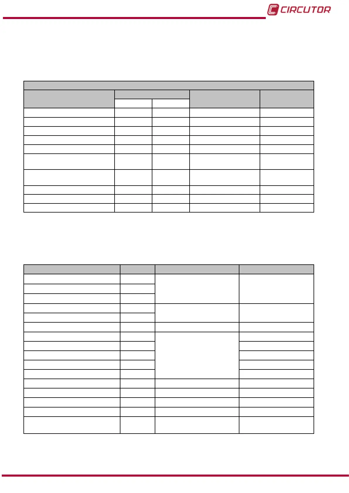
6.3.7.12.- Relay digital outputs
The Maximum Value and Minimum Value conguration variables occupy 2 registers each.
All other variables occupy 1 register each.
Table 43:Modbus memory map: Relay digital outputs.
Conguration of the digital outputs of the relay
Configuration variable
Address
Valid data margin Default value
Output 1 Output 2
Maximum value
(1)
4E48-4E49 4E5C-4E5D Table 44 0
Minimum value
(1)
4E4A-4E4B 4E5E-4E5F Table 44 0
Connection delay (ON) 4E4C 4E60 0 to 999 seconds 0
Disconnection delay (OFF) 4E4D 4E61 0 to 999 seconds 0
Pre-alarm value 4E4E 4E62 0 to 100 % 0
Output status 4E4F 4E63
0 : Normally open
1: Normally closed
0
Interlocking (latch) 4E50 4E64
0 : Unlocked
1: Locked
0
Not used 4E51 4E65 0 0
Variable code 4E52 4E66 Table 21 0
Module no. 4E53 4E67 0 0
(1)
The decimal for the selected variable must be included when programming the maximum and minimum values.
Note: The 12 registers of each output must be written and read at once (as a group), otherwise
it will respond with an error.
Table 44: Units and maximum and minimum values of the programming variables of the digital outputs.
Variable Units Maximum Minimum
Phase-neutral voltage
(4)
V
10000 * voltage ratio
(1)
0
Phase-phase voltage
(4)
V
Neutral voltage
(4)
V
Current mA
10000 *current ratio
(2)
0
Neutral current mA
Frequency
(4)
Hz 7000 4000
Active power
(3)
W
180 000 000
-180 000 000
Apparent power
(3)
VA 0
Total reactive power
(3)
var -180 000 000
Inductive reactive power
(3)
var 0
Capacitive reactive power
(3)
var 0
Power factor - 100 -100
Cos φ º 100 -100
Voltage THD % % 1000 0
Current THD % % 1000 0
Maximum Demand of
Current
mA 10000 *current ratio
(2)
0
193
Instruction Manual
CVM-B100 - CVM-B150