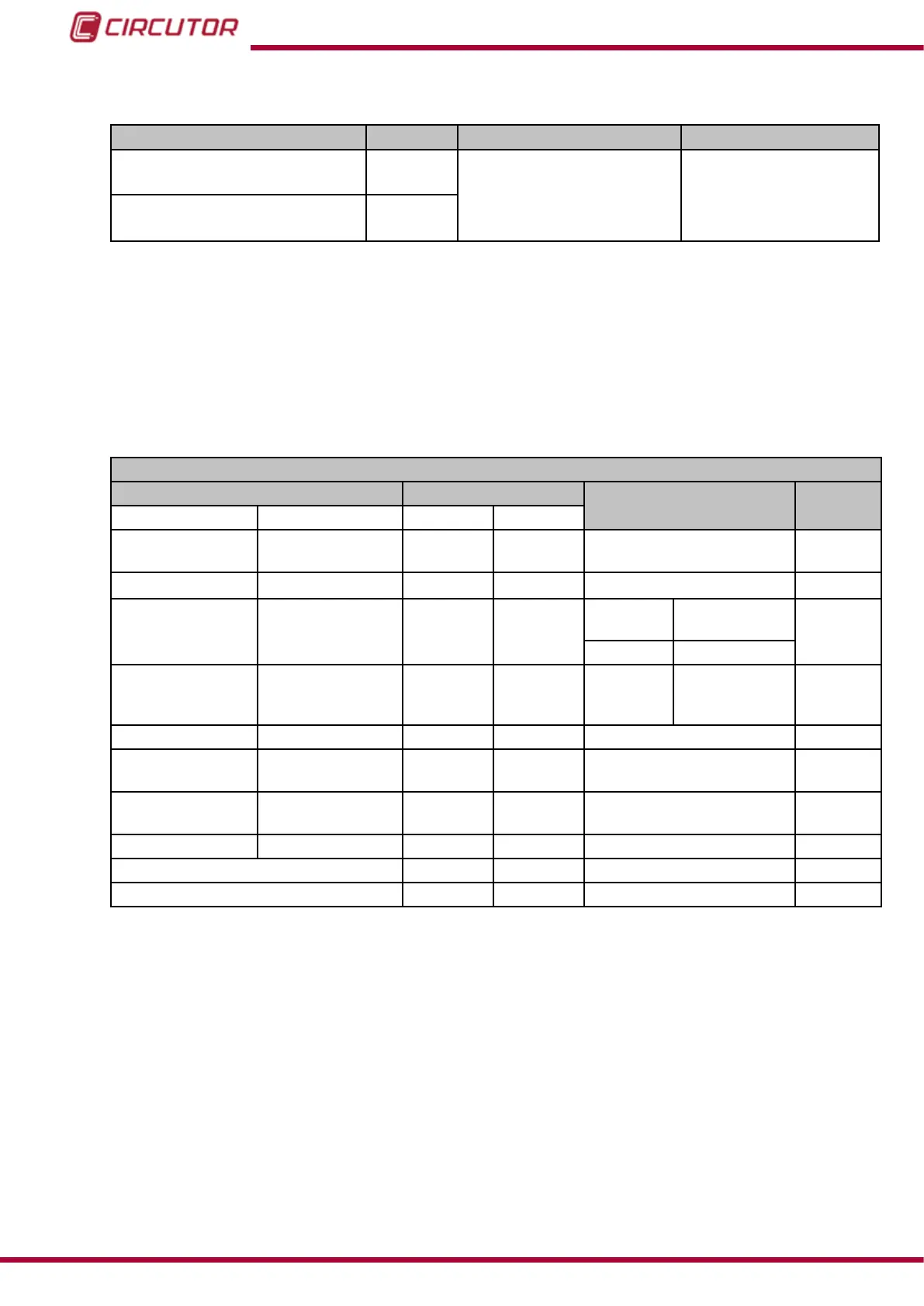
Table 44 ( Continuation): Units and maximum and minimum values of the programming variables of
the digital outputs.
Variable Units Maximum Minimum
Maximum Demand of
Active Power
W
180 000 000 0
Maximum Demand of
Apparent Power
VA
(1)
The voltage ratio is the ratio between the primary and secondary voltage.
(2)
The current ratio is the ratio between the primary and secondary current.
(3)
The three-phase powers accept up to 540 000 000 W.
(4)
Variables with 2 decimals.
6.3.7.13.- Transistor digital outputs
The Maximum Value and Minimum Value conguration variables occupy 2 registers each.
All other variables occupy 1 register each.
Table 45: Modbus memory map: Conguration variables (Transistor digital outputs).
Conguration of Transistor Digital Outputs
Configuration variable
Address
Valid data margin
Default
value
Alarm Impulse output
Output 1 Output 2
Maximum value
(1)
Energy meter
factor
4E20-4E21 4E34-4E35 Table 44
0
Min. value
(1) -
4E22-4E23 4E36-4E37
Table 44
0
Delay in the
connection (ON)
High period 4E24 4E38
Alarm Impulse
output
0
0 a 999 s. 1 a 65536
(2)
Delay in the
disconnection
(OFF)
Low period 4E25 4E39 0 a 999 s. 1 a 65536
(2)
0
Pre-alarm value
-
4E26 4E3A 0 al 100 % 0
Output status - 4E27 4E3B
0 : Normally open
1: Normally closed
0
Interlocking ( latch ) - 4E28 4E3C
0 : Unlocked
1: Locked
0
Not used Not used 4E29 4E3D
0
0
Variable code 4E2A 4E3E Table 21 0
Module no. 4E2B 4E3F
0
0
(1)
When programming the maximum and minimum values, the decimals for the variable selected must be included.
(2)
The programmed value is a multiple of 10 ms, i.e. when programming 1 the impulse will be at its minimum value
of 10 ms.
Note: The 12 registers of each output must be written and read at once (as a group), otherwise
it will respond with an error.
194
CVM-B100 - CVM-B150
Instruction Manual