6.3.7.14.- Digital inputs
The Input Name conguration variable occupies 4 registers.
The Units conguration variable occupies 3 registers.
All other variables occupy 1 register each.
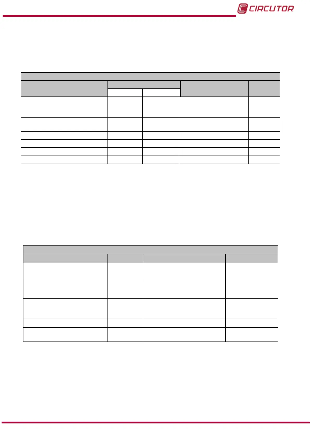
Table 46:Modbus memory map: Conguration variables (Digital Inputs).
Conguration of Digital Inputs
Configuration variable
Address
Valid data window
Default
value
Input 1 Input 2
Mode 4FB0 4FBC
-1: Tariff
0: Logic state
> 0:Impulses
(1)
0
Logic (Logic state) 4FB1 4FBD
0: positive
1: Negative
0
No. of decimals (Impulses) 4FB2 4FBE 0 to 5
0
Not used 4FB3 4FBF 0 0
Input name (impulses)
(2)
4FB4 - 4FB7 4FC0 - 4FC3 8 characters “INPUT”
Units (Impulses)
(2)
4FB8 - 4FBA 4FC4 - 4FC6 6 characters -
(1)
When programming a value of more than 1, programme the impulse operating mode and energy meter factor
for this mode simultaneously.
(2)
the characters must be sent in hexadecimal.
Note: The 11 registers must be written and read at once (as a group), otherwise it will respond
with an error.
6.3.7.15.- Integrated communications
These parameters occupy 1 register each.
Table 47:Modbus memory map: Conguration variables (Communications)
Communications
Configuration variable Address Valid data window Default value
Protocol 2738 0 : Modbus , 1: BACnet 0
Peripheral number 2739 0 to 255 1
Speed 273A
0: 1200 - 1: 2400 - 2: 4800
3: 9600 - 4: 19200 - 5: 38400 -
6: 57600 - 7: 76800 - 8: 115200
4
Parity 273B
0 : No parity
1: Odd parity
2: Even parity
0
Length 273C
1: 8 bits
1
Stop bits 273D
0: 1 stop bit
1: 2 stop bits
0
Note: The 6 registers must be written at once (as a group), otherwise it will respond with an
error.
195
Instruction Manual
CVM-B100 - CVM-B150