B.- Terminals on the lower face
Table 110: List of terminals on the lower face, Analogue inputs/outputs module.
Unit terminals
10: I
1
+, Analogue input 1 14: I
3
+, Analogue input 3
11: I
1
-, Analogue input 1 15: I
3
-, Analogue input 3
12: I
2
+, Analogue input 2 16: I
4
+, Analogue input 4
13: I
2
-, Analogue input 2
17: I
4
-, Analogue input 4
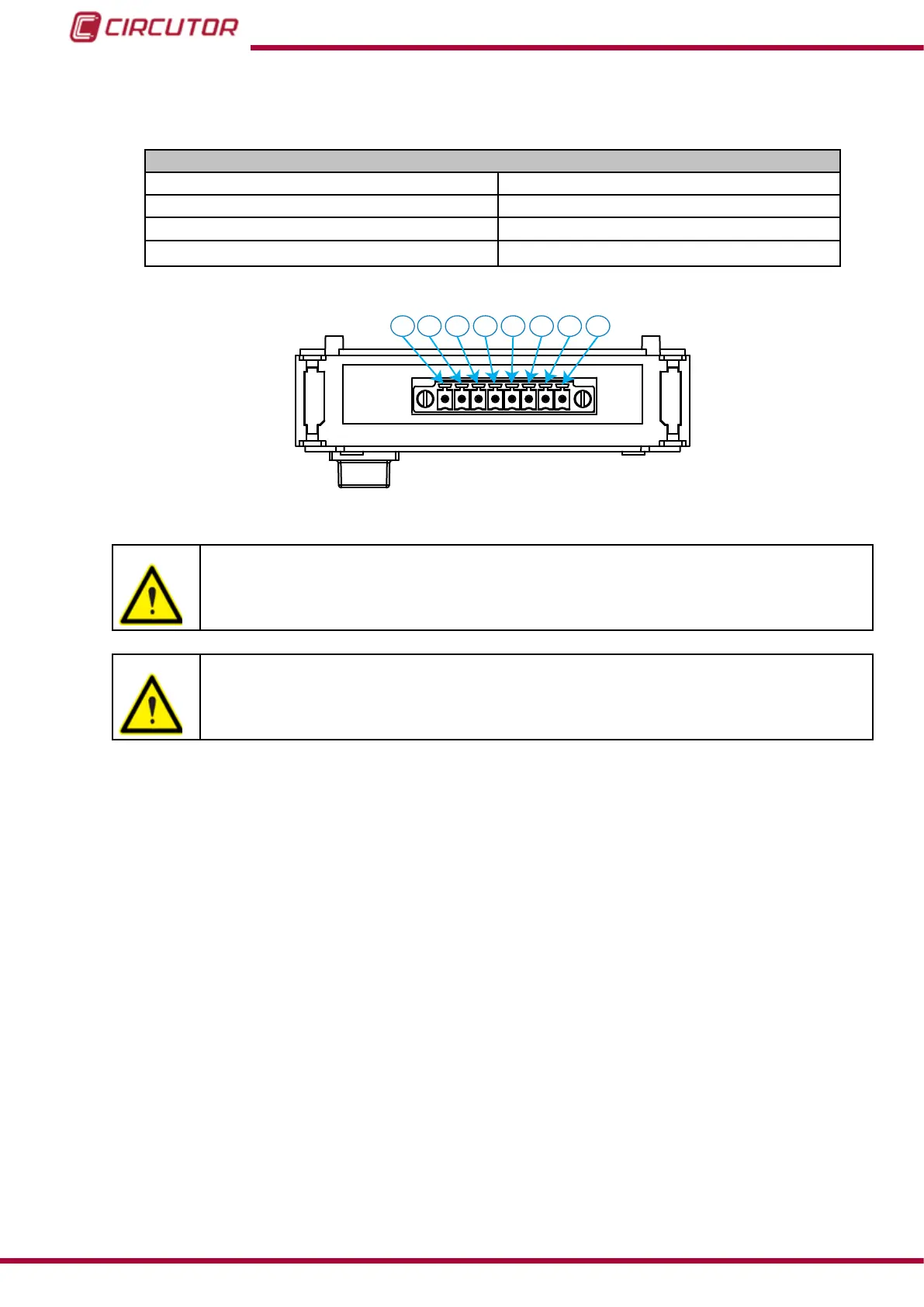
10 11 12 13 1514 16 17
Figure 168:Analogue Input/Output Terminals, lower face.
Respect the input polarities for the unit to work properly.
Do not connect the inputs in series so that the same current passes through all
of them. The unit will not measure correctly.
The inputs must work independently.
244
CVM-B100 - CVM-B150
Instruction Manual