Installation
2-8 9390 Reference manual
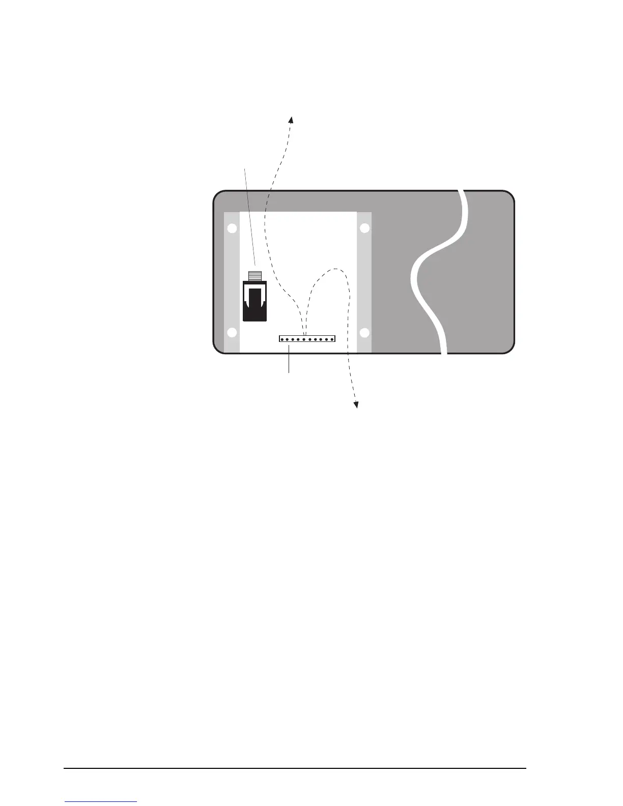
Connecting the control head
L/S
(extension
loudspeaker)
socket
10-pin control cable
connector
Bottom entry
cable path
Top entry
cable path
Figure 2.4
Rear view of control head without cover
plate
The control head chassis is isolated from ground but in
operation may require earthing. See Grounding—RF earth on
page 2-12.
To connect the control head:
1. Remove the four screws that secure the small cover plate
at the back of the control head. Remove the cover. Figure
2.4 shows the back of the control head with the cover
plate removed.
2. If you are connecting an extension loudspeaker, feed the
loudspeaker cable through the foam grommet near the
control head end of the control cable. Note that the
transceiver also has provision for connecting the
extension loudspeaker.
3. Use the cable clamp to attach the control cable to the
inside surface of the cover.