Connectors, Switches, and LED Status Indicators 4-3
System Board Connectors
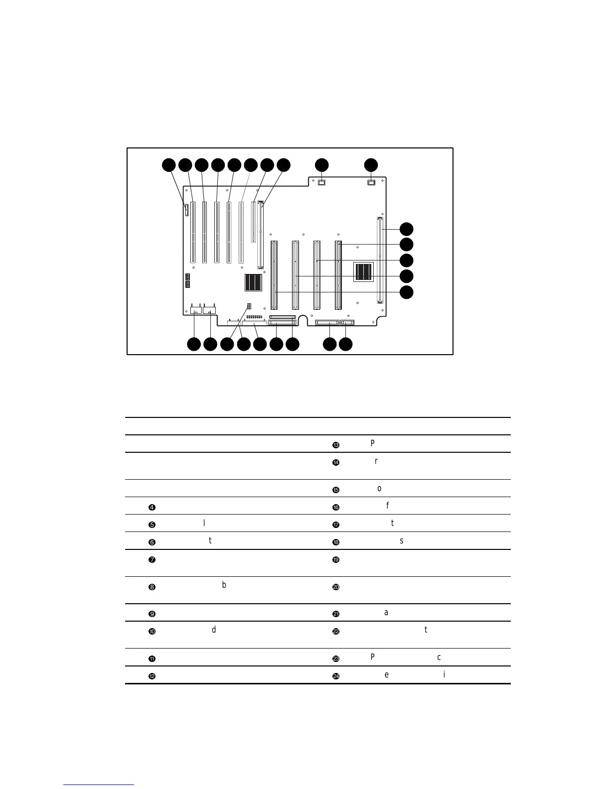
Figure 4-2 shows the system board connectors for the ProLiant ML570 server. Table 4-2 shows
the corresponding connector descriptions.
1 2 9 103 4 5 6 7 8
11
1617
12
13
14
15
18192021222324
Figure 4-2. System board connectors
Table 4-2
System Board Connectors
Item Connector Item Connector
➊
Hot-plug connector
Processor slot 2
➋
PCI slot, 33-MHz/64-bit
(non-hot-pluggable)
Processor slot 3
➌
PCI slot, 33-MHz/64-bit
Processor slot 4
PCI slot, 33-MHz/64-bit
CPU fan
PCI slot, 66-MHz/64-bit
Diskette drive
PCI slot, 66-MHz/64-bit
High density IDE drive (not used)
PCI slot, 33-MHz/32-bit
(non-hot-pluggable)
IDE CD-ROM drive
Peripheral board slot
(non-hot-pluggable)
Power supply backplane sense
connector
Not used
I/O fan
Not used
Virtual power button connector for the
Remote Insight Board (RIB)
Memory board slot
Power supply connection
Processor slot 1
Power supply connection
 Loading...

