Connectors, Switches, and LED Status Indicators 4-13
Interlock Status LED Indicators
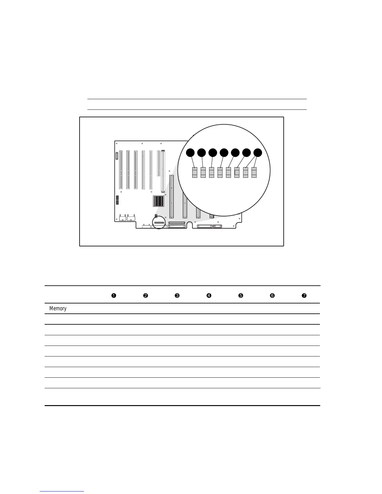
Improperly seated components in the interlock chain cause the LED associated with the fault
origination point to illuminate on the system board. Figure 4-10 shows the location of the
interlock LED indicators and Table 4-10 identifies the point of the hardware connection fault.
IMPORTANT: This server is not equipped with chassis door or access panel interlocks.
IL 0
IL 1
IL 2
IL 3
IL 4
IL 5
IL 6
1 2 3 4 5 6 7
Figure 4-10. Interlock LED indicators on system board
Table 4-10
System Board Interlock LED Indicators
Fault of Interlock
Error
Memory board OnOnOnOnOnOnOn
Processor 1 Off On On On On On On
Processor 2 OffOffOnOnOnOnOn
Processor 3 Off Off Off On On On On
Processor 4 Off Off Off Off On On On
Peripheral board Off Off Off Off Off On On
P/S backplane board Off Off Off Off Off Off On
No interlock error Off Off Off Off Off Off Off
Note: Only the left LED indicator in any row can provide a valid indication of error. After ensuring that the server is powered
down and the power cables are disconnected from all the power supplies, reseat the device associated with the left LED.