Removal and Replacement Procedures 2-55
Power On/Standby Switch and Cable Assembly
To remove the Power On/Standby switch and cable assembly:
1. Perform the preparation procedures. See “Preparation Procedures” earlier in this chapter.
2. Remove the access panel. See “Access Panel (Tower and Rack)” earlier in this chapter.
3. Remove the hard drive fan air baffle. See “Hard Drive Fan Air Baffle” earlier in
this chapter.
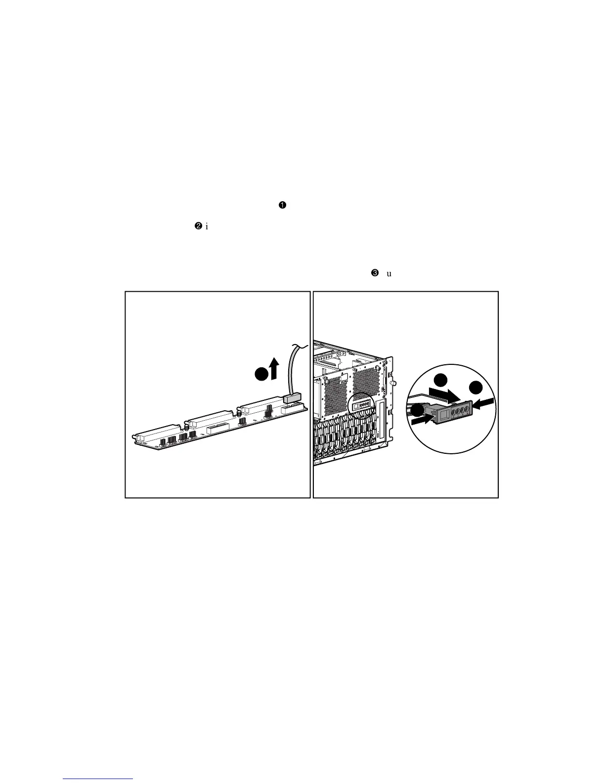
4. Disconnect the power switch cable
from the power backplane board.
5. Press the tabs
inward on both sides of the switch.
NOTE: Compaq recommends pressing the tabs with a 4-mm flat-blade screwdriver.
6. With the tabs released, pull the switch and cable assembly
out the front of the bezel.
2
1
2
3
Figure 2-45. Removing the Power On/Standby switch and cable assembly
Reverse steps 1 through 6 to replace the Power On/Standby switch and cable assembly.