Connectors, Switches, and LED Status Indicators 4-11
Power Switch and Front Panel LED Indicators
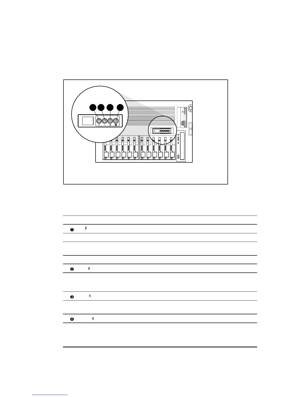
The front panel Power On/Standby switch is embedded with four LED indicators. Figure 4-8
shows the location of the LED indicators on the front panel. Table 4-8 identifies each LED and
describes conditions for all of the LED indicator modes.
1 2
3 4
Figure 4-8. Front panel LED indicators
Table 4-8
Front Panel Status LED Indicators
Item Description Status Condition
Power LED Green System power on
Amber System power in standby
Amber
(flashing)
Temporary shutdown (15 seconds) due to thermal event
Off System power off
Memory Green All memory modules (DIMMs) and processors operational
Amber
(flashing)
One or more DIMMs or processors have failed—check the
Internal Diagnostics Display (IDD). See “Internal Diagnostics
Display” later in this section.
Fans Green All fans operational
Amber
(flashing)
One or more fans have failed—check fan LED indicators.
See “Hot-Plug Fan LED Indicators” later in this section.
Power Supplies Green All power supplies operational
Amber
(flashing)
One or more power supplies have failed—check
power supply LED indicators. See Table 4-14 “Hot-Plug
Power Supply Diagnostic LED Indicators” later in this
section.