Removal and Replacement Procedures 2-57
System Board
To remove the system board:
1. Perform the preparation procedures. See “Preparation Procedures” earlier in this chapter.
2. Remove the electronics drawer. See “Electronics Drawer” earlier in this chapter.
3. Remove the insulator basket. See “Insulator Basket” earlier in this chapter.
4. Disconnect and remove all expansion boards from the system board. Place these boards on
a nonconductive work surface. See “I/O Expansion Boards” earlier in this chapter.
5. Remove the peripheral board. See “Peripheral Board (Non-Hot-Pluggable)” earlier in
this chapter.
6. Remove the memory expansion board. See “Memory Expansion Board” earlier in
this chapter.
7. Remove all processors and terminator boards. See “Processors, Terminator Boards, and
Processor Cage” earlier in this chapter.
8. Remove the processor cage. See “Processor Cage” earlier in this chapter
9. Disconnect all signal and power cables from the system board. See “Cable Routing
Diagrams” earlier in this chapter.
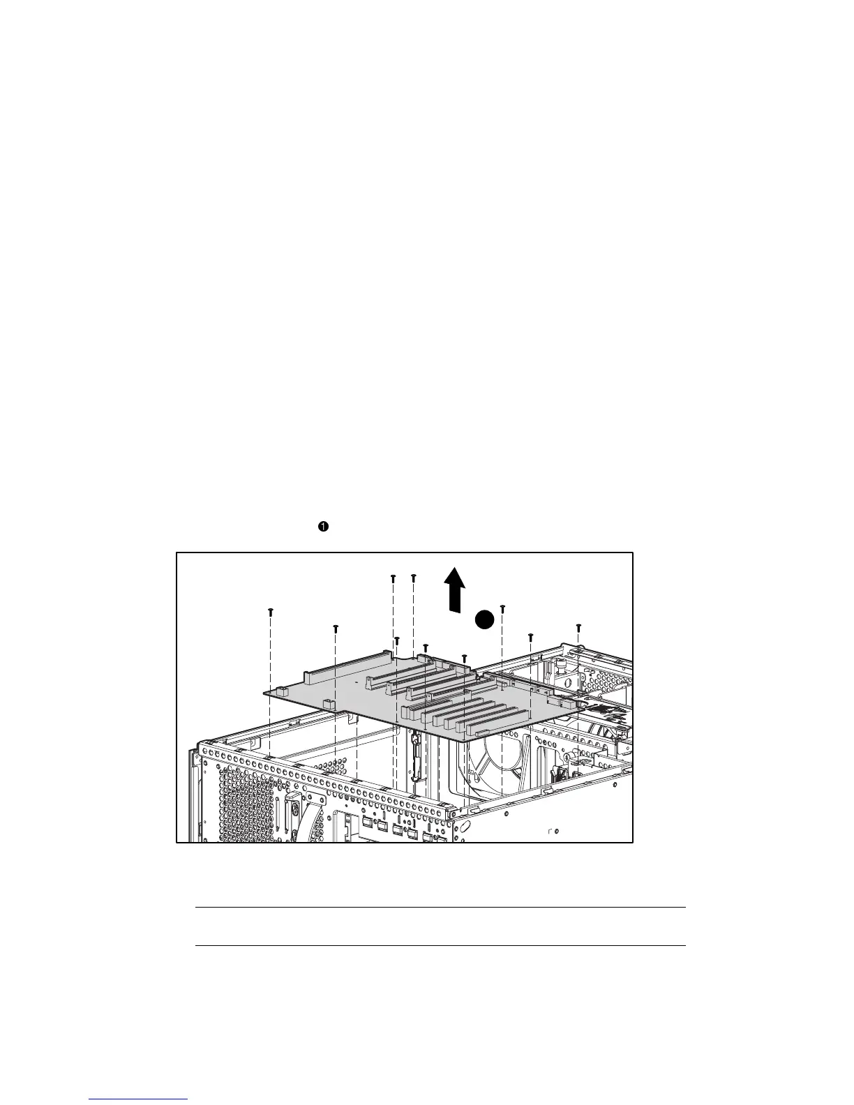
10. Remove the ten T-15 screws securing the system board to the electronics drawer.
11. Lift the system board
from the electronics drawer.
1
Figure 2-47. Removing the system board
Reverse steps 1 through 11 to replace the system board.
IMPORTANT: Change the switch 1 and switch 2 settings to match the switch settings on the board
being replaced. Install all removed boards onto the replacement system board.