Connectors, Switches, and LED Status Indicators 4-9
System Board ID/Miscellaneous Switch (SW6)
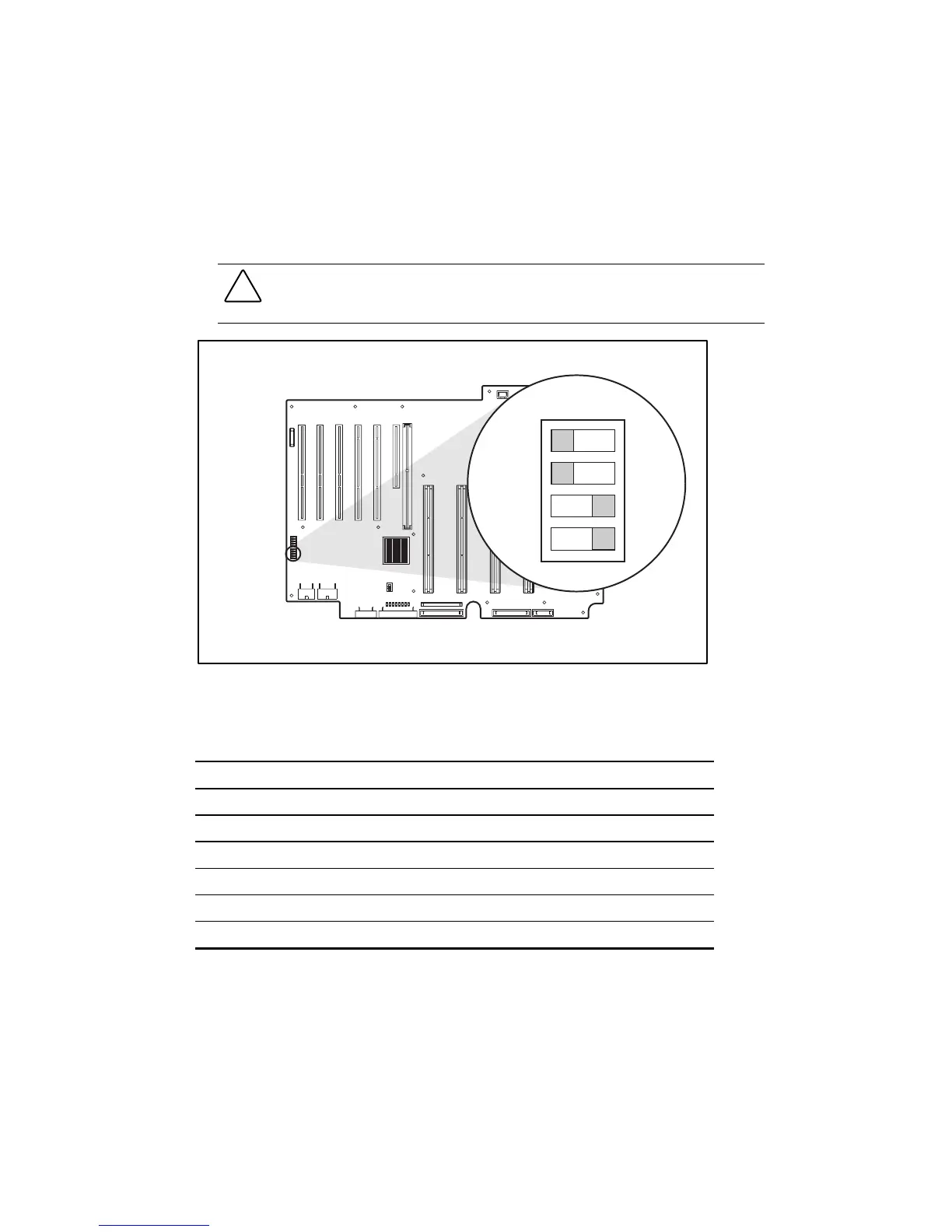
Figure 4-7 shows the location of the system board ID/miscellaneous switch (SW6). Switches 3
and 4 are used for system chassis identification. Switch 1 is used to control booting from a spare
processor. Switch 2 is used to disable the system board interlocks. Table 4-7 identifies the
functions and settings of each switch.
CAUTION: These settings are factory-set and do not need to be adjusted. They are only shown
here for identification and diagnostics. Refer to the Compaq ProLiant ML570 Troubleshooting
Guide for additional information.
off
1
2
3
4
Figure 4-7. System board ID/miscellaneous switch (SW6)
Table 4-7
System Board ID/Miscellaneous Switches (SW6)
Switch Function Settings
1 Hot spare boot enable Off = Enables hot spare boot
On = Disable hot spare boot
2 Interlock enable Off = Interlock enabled
On = Interlock disabled
3 System chassis ID On = ProLiant ML570 server chassis
4 System chassis ID On = ProLiant ML570 server chassis