Removal and Replacement Procedures 2-35
If the electronics drawer is to be removed completely from the ProLiant ML570 server, follow
these additional steps:
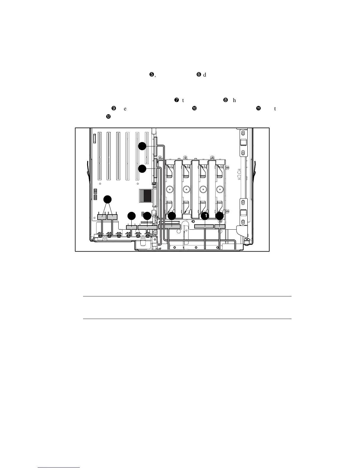
7. Disconnect the SCSI port 1
, and SCSI port 2
data cables from the peripheral board,
then pull the two cables out through the two openings located at the back of the
electronics drawer.
8. Disconnect the 2 power supply cables
, the I/O fan cable
, the power supply backplane
sense cable
, the IDE CD-ROM drive cable
, the diskette drive cable
, and the CPU
fan cable
.
7
8 9 10 11 12
5
6
Figure 2-27. Disconnecting the cables from the electronics drawer
9. Disconnect and remove all memory modules, processors, and PCI expansion boards from
the system board. Place these components on a nonconductive work surface.
Reverse steps 1 through 9 to replace the electronics drawer.
IMPORTANT: Be sure to install all previously removed memory modules, processors, and PCI expansion
boards onto the new electronics drawer. Change the switch settings to match the switch settings on the
system board being replaced.