Appendix A: RAU Upgrades P/N 709C011801 Page 131
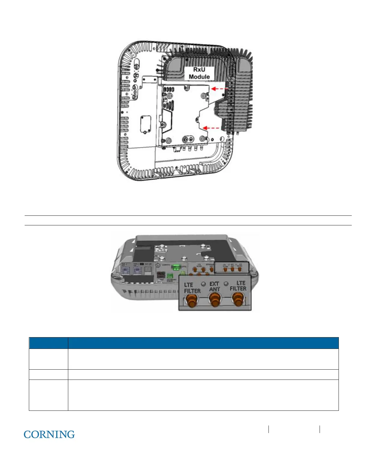
Figure 6-16. RxU Module Assembly
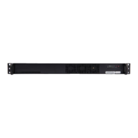
3. If required by site planner - connect the filter to the RF filter connectors on the RxU. Refer to Figure 6-17 for location of RxU
filter connections.
Note: Refer to section 5.2.3 for Cavity Filter installation and connections.
Figure 6-17. Assembled RxU Interfaces
4. Verify that RAU LEDs on, on front cover (see Figure 6-18) indicate normal operation status:
LED Description
LINK Steady Green - Optical link power to/from the connected remote is normal
Blinking Green - Optical power is lower than required
POWER Steady Green - Input power within required range detected
RUN Steady Green - Module SW has initialized and is up and running
Blinking Green – Fault detected
Off – Power off