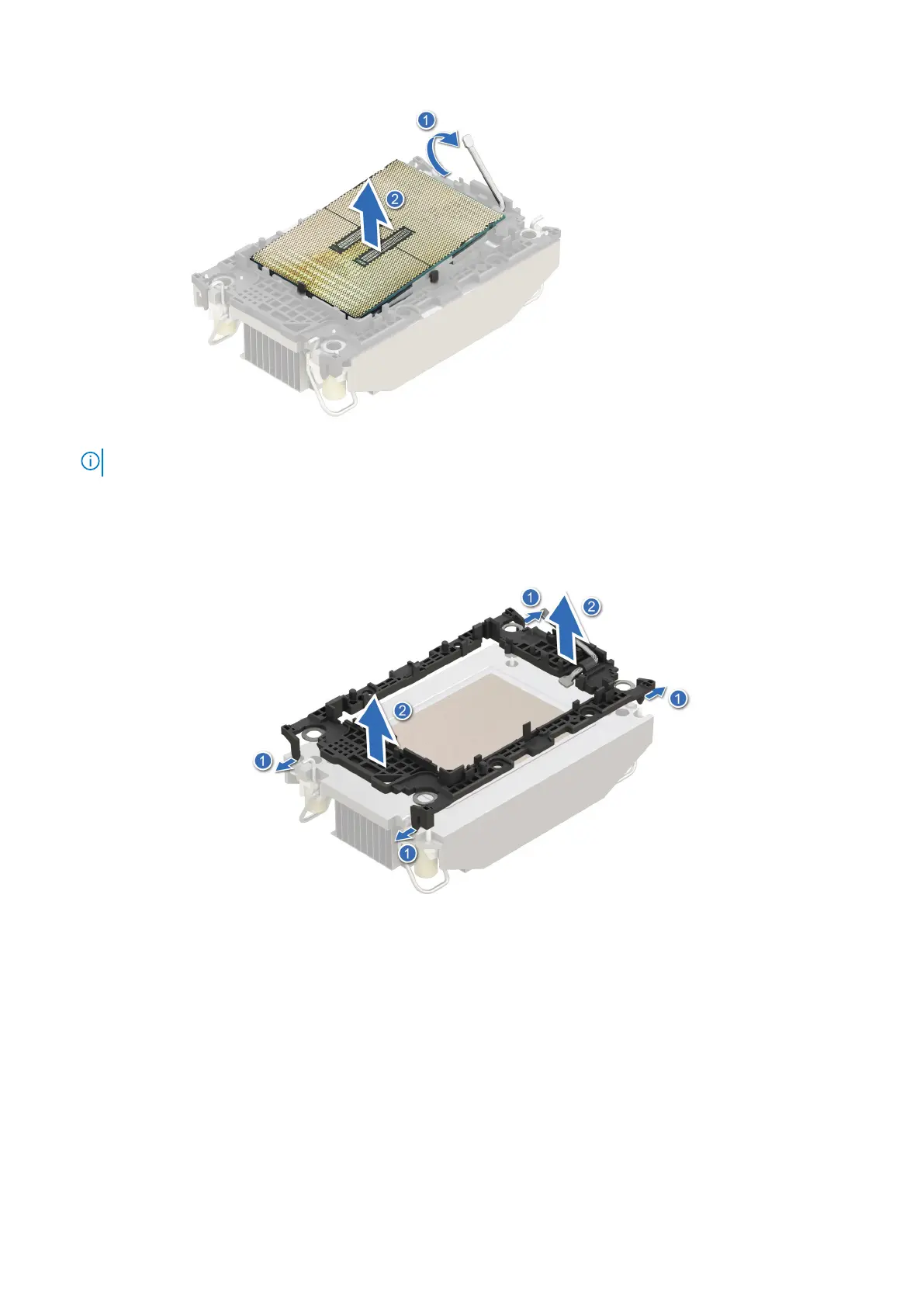
NOTE: Ensure to return the TIM break lever back to original position.
4. Using your thumb and index finger, first hold the retaining clip release tab at the pin 1 connector, pull out the tip of the
retaining clip release tab, and then lift the retaining clip partially from the heat sink.
5. Repeat the procedure at the remaining three corners of the retaining clip.
6. After all the corners are released from the heat sink, lift the retaining clip from the pin 1 corner of the heat sink.
Figure 85. Removing the retaining clip
Next steps
Replace the processor.
Installing the processor
Prerequisites
1. Follow the safety guidelines listed in the Safety instructions.
2. Follow the procedure listed in Before working inside your system.
3. Remove the 2U sled from 1U node
114
Installing and removing system components

 Loading...


