Table 75. System board connectors description
Item Connector Description
1 SL4_CPU1_PA4 PCIe connector 4
2 SL3_CPU1_PB4 PCIe connector 3
3 SL2_CPU1_PB3 PCIe connector 2
4 SL1_CPU1_PA3 PCIe connector 1
5 J_R1_PWR PCIe Extension Power
6 SYS_PWR_CONN1 Power connector 1
7 SYS_PWR_CONN2 Power connector 2
8 PIB Signal PIB Signal
9 IO_RISER1 Riser 1 connector
10 Reserved(INT_USB1) Reserved for debug purpose
11 Coin cell battery Coin cell battery
12 Micro-USB Serial Micro-USB Serial Port
13 iDRAC_DIRECT iDRAC Direct Port
14 SYS_ID System ID button
15 Display Display Port
16 USB USB 3.0 connector
17 iDRAC RJ45/Dry Input iDRAC RJ45/Dry Input
18 POWER Power button
19 BOSS-N1 BOSS-N1 M.2 connector
20 MIC_CON Smart NIC connector
21 TPM TPM connector
22 Reserved(IO_RISER2) Riser 2 connecctor
23 JUMPER BIOS password and NVRAM jumper
24 A4, A6, A2, A8 DIMM slots (A4, A6, A2, A8)
25 CPU Processor socket
26 A5, A3, A7, A1 DIMM slots (A5, A3, A7, A1)
NOTE: J_R1 PWR1 and J_R1_PWR2 is for PCIE Riser1 Slot1 Slimline power and Slot2 Slimline power. They are located on
2U PDB board
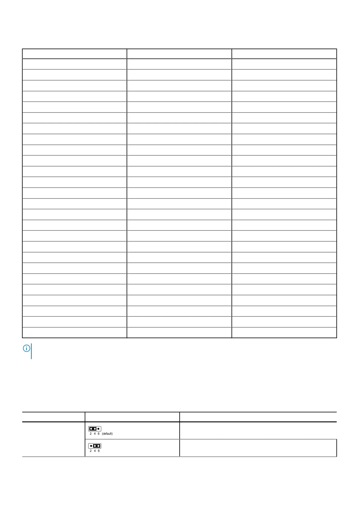
System board jumper settings
For information about resetting the password jumper to disable a password, see the Disabling a forgotten password section.
Table 76.
System board jumper settings
Jumper Setting Description
PWRD_EN The BIOS password feature is enabled.
The BIOS password feature is disabled. The BIOS password is
now disabled and you are not allowed to set a new password.
Jumpers and connectors 129

 Loading...


