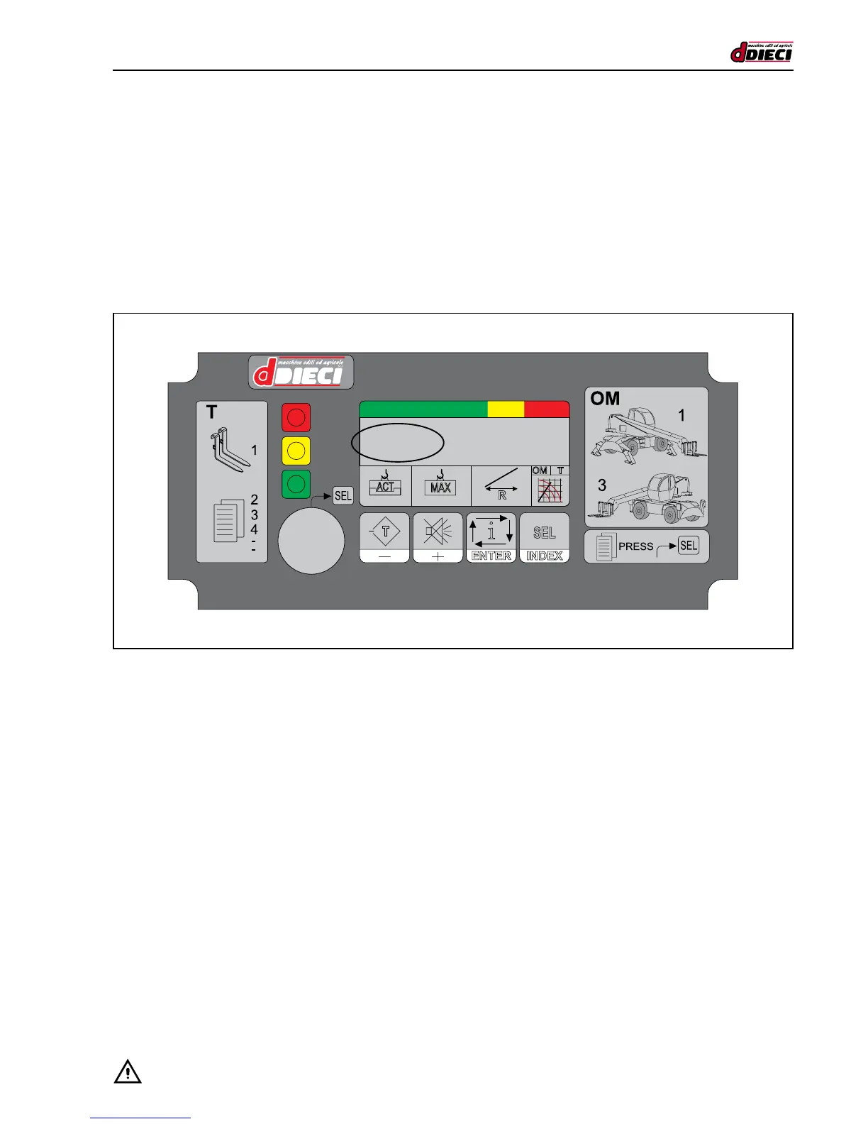
ATTACHMENT AND OPERATING MODE DISPLAY
The operating mode setting (OM) is automatic because selected by external microswitches. On the normally displayed main
page, the Selected Attachment Table (T) and the Operating Mode (OM) of the machine are displayed in the highlighted area in
the form of numbers.
In the example in the gure, the indicating working condition is:
OM = 1
Stabilisers 360°
T = 1
Forks
Forks
Stab. 360°
With reference to the symbols on the panel, the possible selections are as follows:
Main (Automatic) OM:
1 = Stabilisers 360°
2 = Front Stabilisers
3 = Tyres 360°
4 = Front Tyres
T (Manual) that can be selected on the panel:
1 = Forks 0 = Basket 800 Kg. I = ..................
2 = Jib 2500 A = Centring handler L = ..................
3 = Basket 300 Kg. B = Basket 1000 Kg. M= Bas_centring hand.
4 = Jib 4500 C = Jib 1300 N= Cest2002P
5 = Winch 3.8 T D = .................. X= ..................
6 = Winch 2.5 T E = ..................
7 = Basket500_AFDM F = ..................
8 = Jib 1000 G = Hook
9 = POS-NEG boom H = ..................
NOTE: Not every machine can assemble the complete range of attachments.