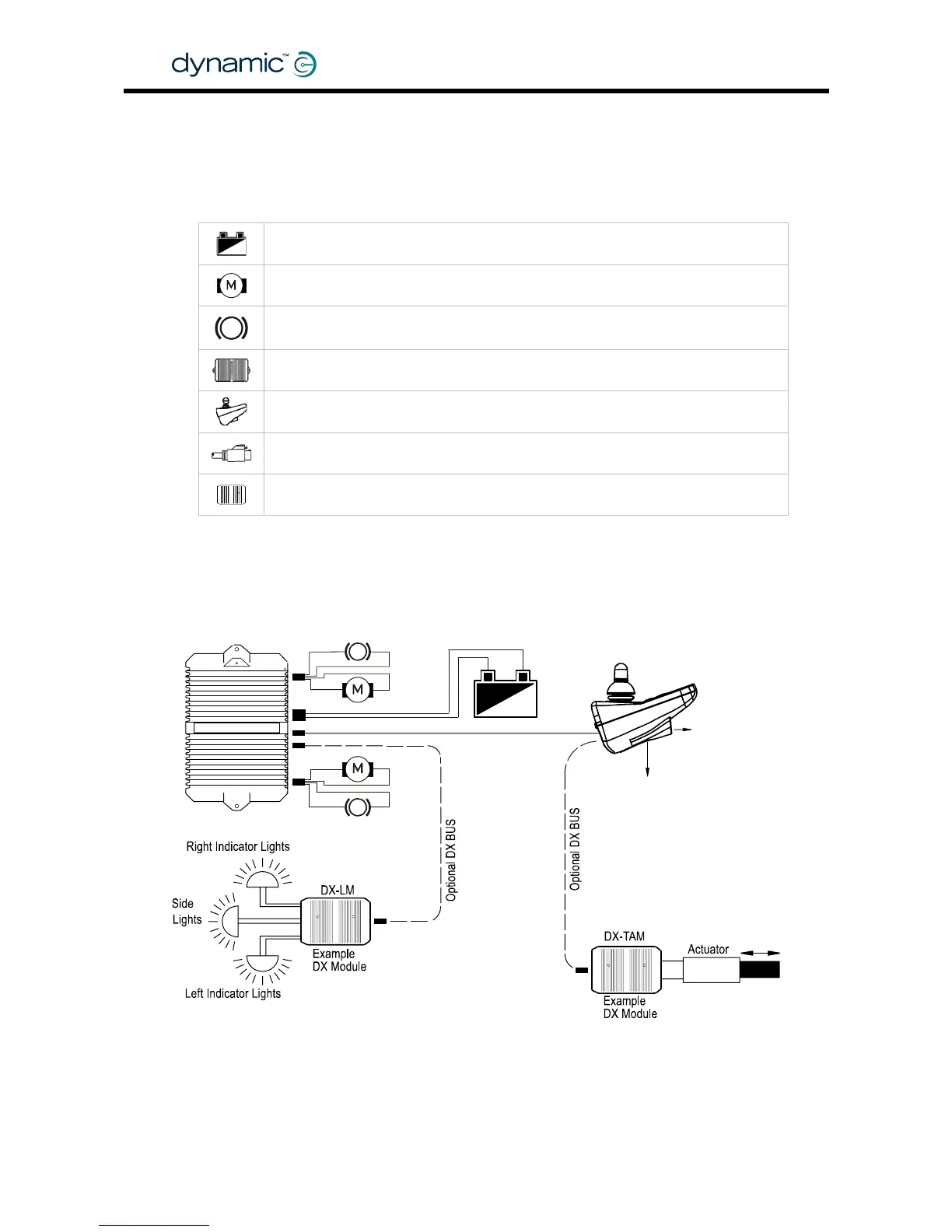
2 A typical DX powerchair setup
A standard powerchair installation with the DX System consists of the following
electrical parts:
The Batteries (section 2.2)
The Motors (section 2.3)
The Parkbrakes (section
2.4)
A DX Power Module (chapter
4)
A DX Master Remote (chapter
5)
The DX BUS cables (section
3.1)
Optional: Actuator or Lighting Modules (chapter
6)
P
PB1
M1
P
PB2
M2
P
To HHP
or Wizard
24V Batter