MT
2.4.2.3 Two 12V parkbrakes
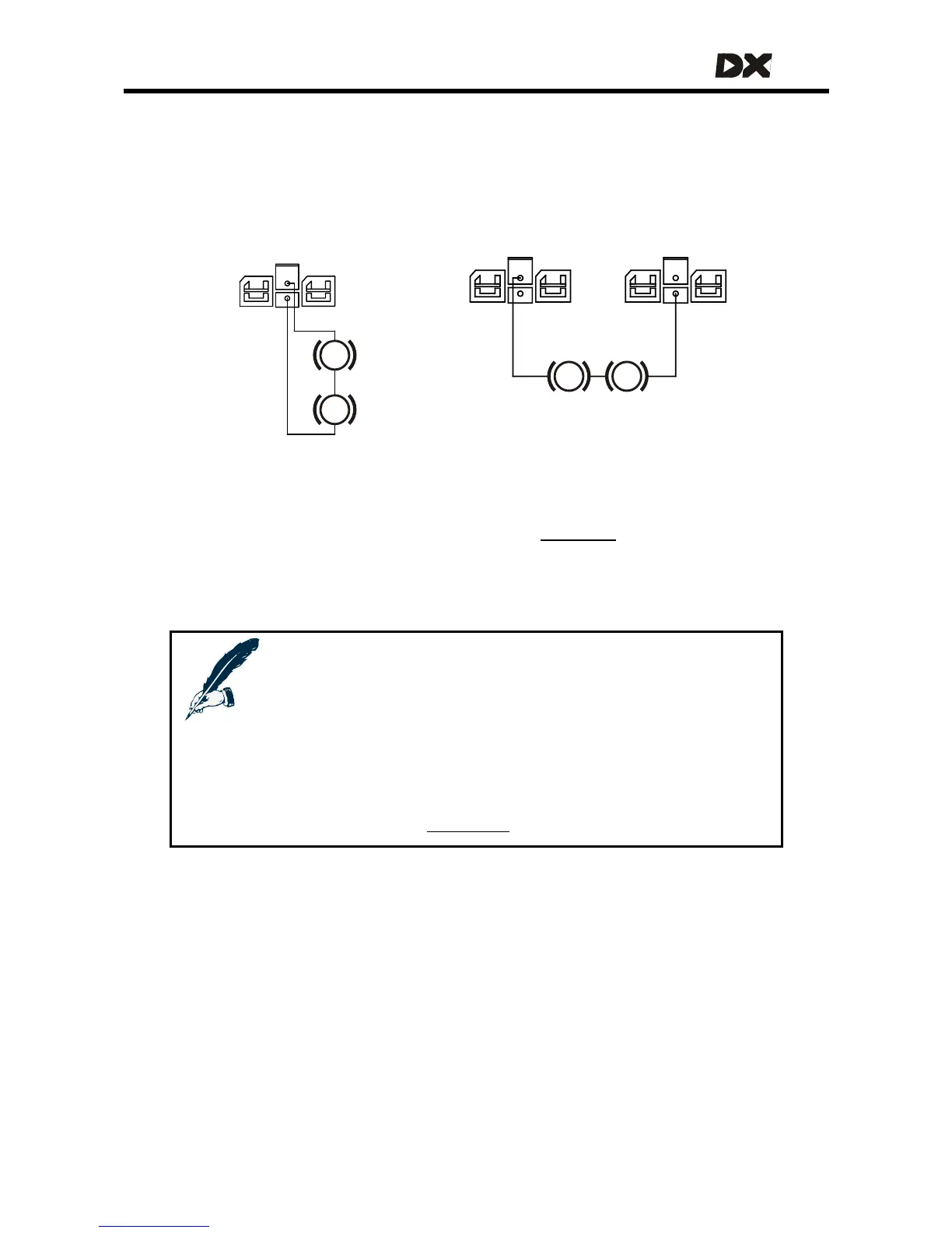
If the powerchair has two 12V parkbrakes, both can be driven from a single 24V
output by connecting the 12V parkbrakes in series. Alternatively, the 12V parkbrakes
can be connected to both parkbrake outputs. In the latter case the parkbrakes will
be driven from the PB+ output of M1.
For both these configurations the DX Power Module
Park Brake parameter (see
section
4.3.3.1) must be set to Single.
12V
Park
Brake
M1
12V
Park
Brake
M1
12V
Park
Brake
12V
Park
Brake
PB+ PB-
P
P
P P
M2
12V parkbrakes configuration 2 12V parkbrakes configuration 1
Notes:
Configuration 1: if the park brakes are connected to M2 instead of
M1, a Left Parkbrake Fault (flash code 5) will occur.
Configuration 2: if PB+ is connected to M2 instead of M1, a Left
Parkbrake Fault (flash code 5) will occur.
Both configurations: if the Park Brake parameter is set to Dual, a Right
Parkbrake Fault (flash code 6) will occur.
See also section
9.6: Flash codes
21