MT
4 The DX Power Module
The DX Power Module converts the speed and direction signals generated by a DX
Remote into high current outputs. These outputs drive the motors and activate the
parkbrakes.
The Power Module must be connected to:
• The DX BUS (see chapter
3)
• The battery (see section
2.2)
• The motors (see section
2.3)
• The parkbrakes (see section
2.4).
The Power Module is fully programmable for a wide range of powerchair types and
user needs.
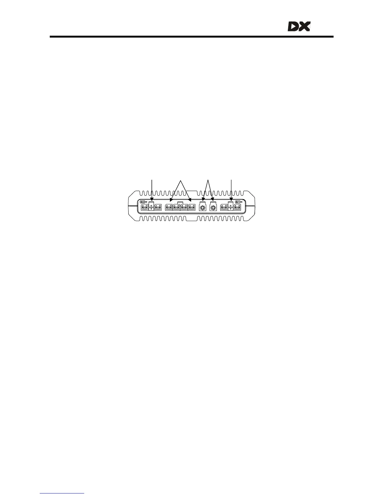
M/PB-2 Batter
DX BUS M/PB-1
4.1 General Power Module features
• Digital motor control
• Supply Voltage compensation
• Motor resistance and load compensation (see 4.3.2.3)
• Tracking (veer) compensation (see
4.3.2.5)
• Smart current limiting and temperature limiting (see
4.3.2.1 and 4.3.4.7)
• Left/Right Motor swap option to facilitate motor cabling (see
4.3.2.7)
• Motor connector polarity swap for different motor polarity options (see
4.3.2.8)
• Single or dual parkbrakes (see
2.4.2)
• Programmable parkbrake delay (see
4.3.3.2)
• Dynamic braking in neutral
• Protected against external events such as:
o reverse battery polarity
o battery undervoltage and overvoltage (see
4.3.4.6)
o motor or parkbrake overload (see
4.3.2.9)
o external short circuits
• Extensive range of powerchair system safety and protection features such as:
o open circuit motor detection
o open and short circuit Park Brake detection
o controlled speed reduction to a stop if a fault is detected (see
4.3.2.6)
o protected against runaway in the event of an internal hardware failure
29