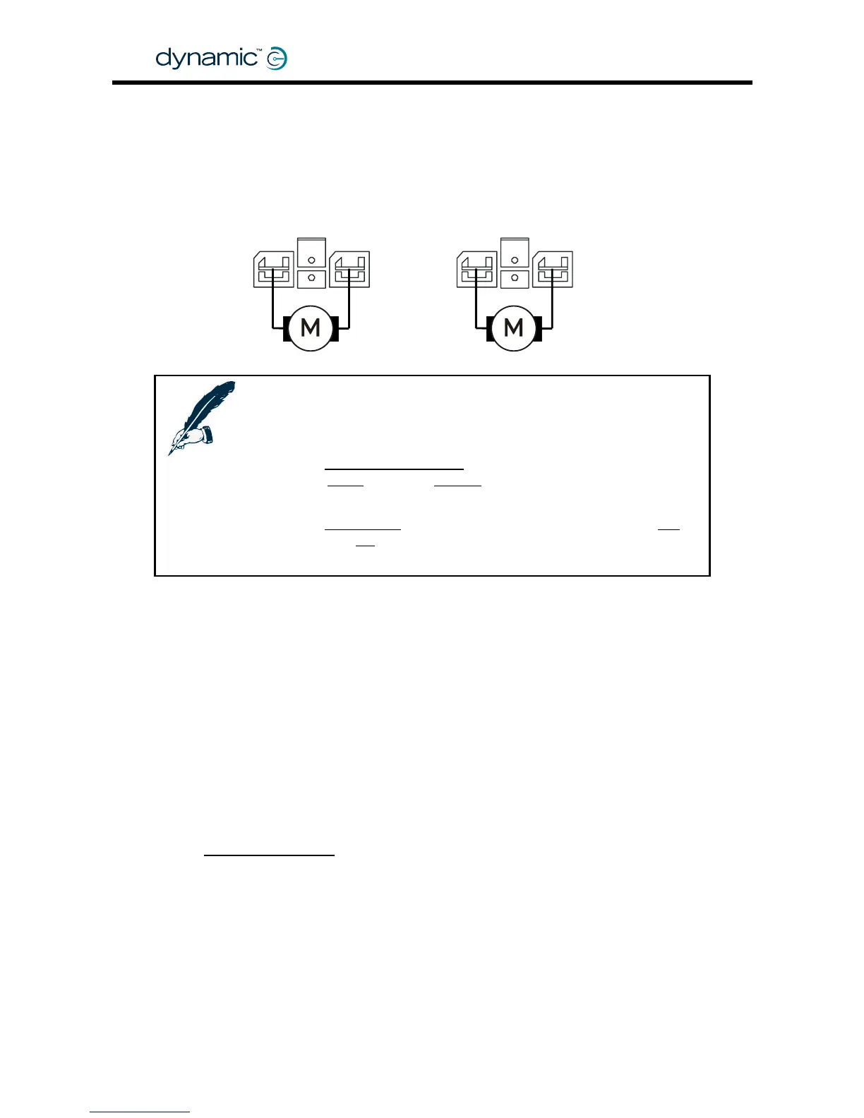
2.3.2 Motor connections
The DC motor cables must be connected to the Motor/Parkbrake connectors of the
DX Power Module.
M2 / Right M1 / Left
+
-
+
-
Notes:
1. Keep the motor cables as short as practical to minimise
voltage drops in the cable.
2. If the
Left/Right Motor Swap parameter (see section 4.3.2.7) is
set to
Swap instead of Normal, the Power Module will assign
M1 to the Right motor and M2 to the Left motor.
3. If the
Motor Invert parameter (see section 4.3.2.8) is set to Yes
instead of
No, the polarity of the + and - terminals will be
swapped.
2.3.3 Motor resistance
The resistance of different motor types varies typically between 20 and 350 mΩ.
The DX Power Module must know what the motor resistance is because the motor
resistance determines the internal voltage drop in the motor when the motor is under
high load (when the motor needs a lot of current to do a task).
If the voltage inside the motor drops too much, the performance of the powerchair
will be decreased:
• It will feel unresponsive
• It will slow down or stop when it tries to go up a slope or up a sidewalk edge.
The DX
Load Compensation feature compensates for the voltage drop in the motor.
If the motor has a high resistance, the Power Module applies a higher voltage to the
motor terminals in high load conditions. This prevents a loss of performance.
To find out how to determine the motor resistance and how to program Load
Compensation, see section
4.3.2.3.
GBK60348
: Issue 1 – October 2007
18