MT
3 The DX BUS
DX BUS is the interface (the way the modules "talk" to each other) that connects all
the DX components together.
The DX BUS interface is based on CAN-Bus technology, which is commonly used in
safety critical applications like automotive and industrial control networks. CAN
provides extremely robust data reliability with excellent error detection and correction
capabilities. This makes the DX BUS a safe and fault tolerant data network.
The DX BUS also distributes power to the DX Modules and can safely carry up to 12
Ampere continuously.
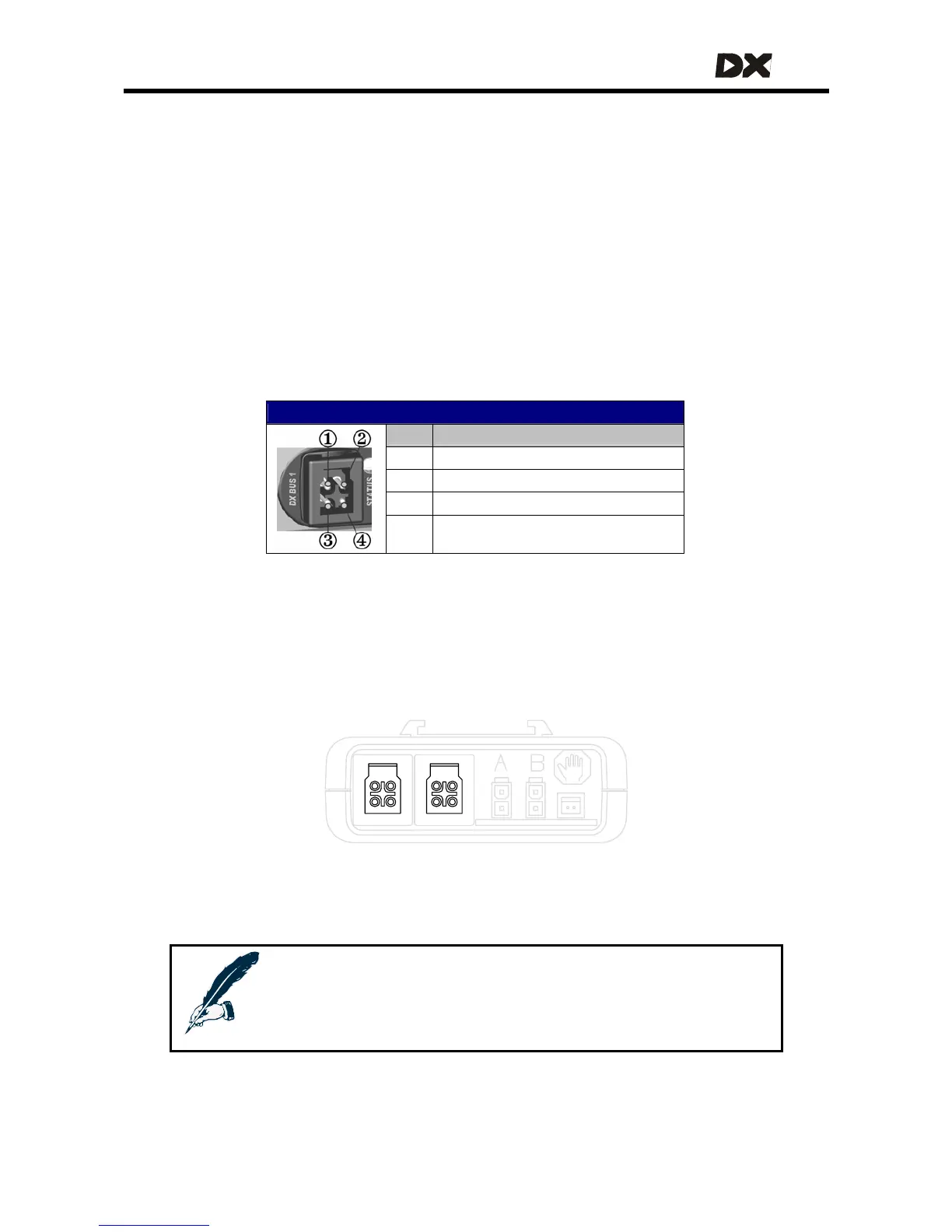
DX BUS Connector Pinout
Pin Function
1 Communications – CANL
2 Communications – CANH
3 DXB+ (24 V, fused)
4 DXB- (0 V)
CAN-H and CAN-L are used for communication between the modules.
DXB+ and DXB- supply power to the modules and to the loads connected to them.
The maximum continuous current over the DX BUS DXB+ and DXB- wires is 12A.
Most DX devices have two DX BUS connectors
Notes:
Dynamic recommends to fit unused DX BUS connectors with a
GME64909 DX BUS Connector Cover. This also complies with
ISO 7176 requirements.
25