MT
2.4 The parkbrakes
The parkbrakes make sure that the powerchair does not move when it is
not actively driven or when the power is turned off.
For safety, parkbrakes are always applied unless they are actively
released, either by the Power Module or manually with a parkbrake
release switch.
P
Note:
If the parkbrakes are not connected to the DX Power Module, the DX
System detects a Parkbrake Fault (see
9.6) and prevents driving.
2.4.1 Parkbrake types
• Fail-safe electro-magnetic parkbrakes attached to each motor
• 24V or 12V
• 1A – 2A maximum current per parkbrake (dependent on the Power Module used,
see the PM manual for the correct specification)
2.4.2 Parkbrake configurations
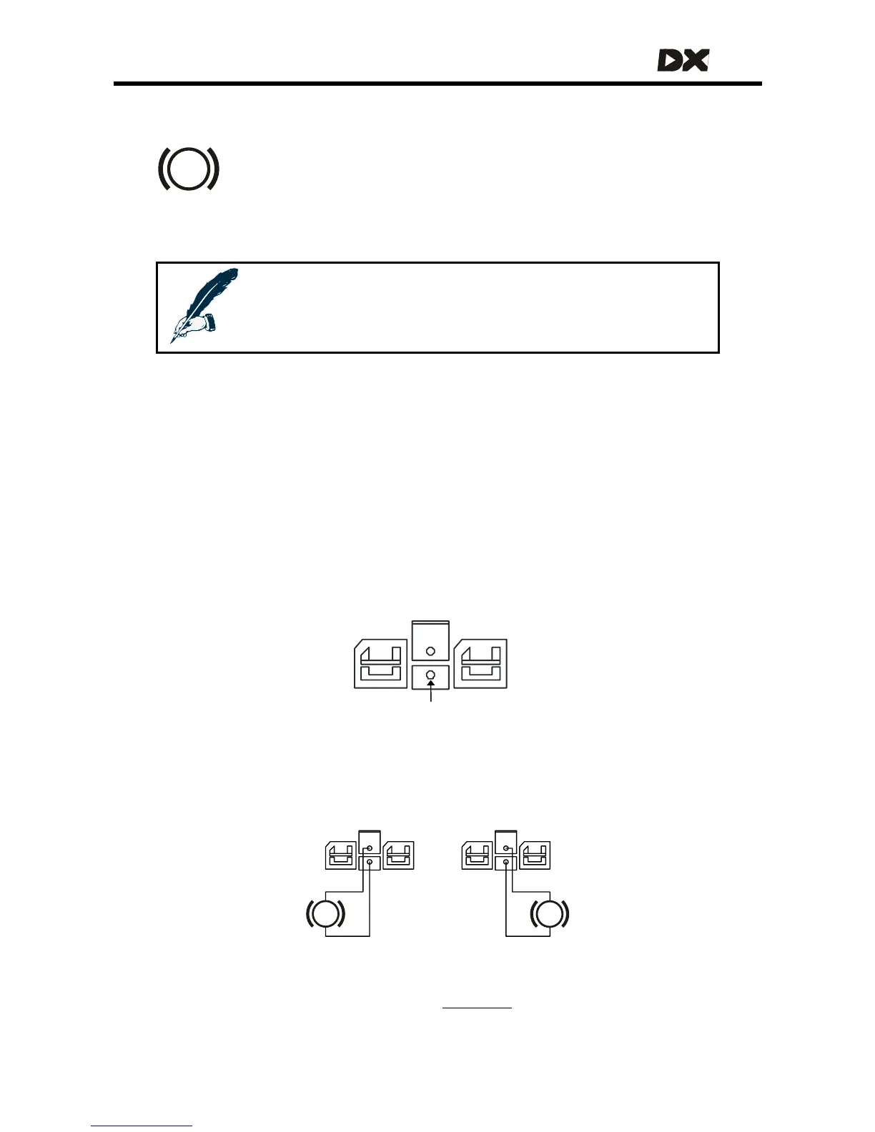
The parkbrake connection pins are located in the motor connectors of the DX Power
Modules.
PB+
PB-
2.4.2.1 Two 24V parkbrakes – Dual, M1 and M2
In the dual configuration each parkbrake is driven from a separate output.
For this configuration the DX Power Module
Park Brake parameter (see section
4.3.3.1) must be set to Dual.
P
P
24V
Park
Brake
24V
Park
Brake
M2
M1
19