3.2 DX BUS Module connection layout
DX Modules normally have one or two DX BUS sockets for system interconnections.
Smaller DX Modules can have a permanently mounted cable ending in a DX BUS
plug, instead of DX sockets.
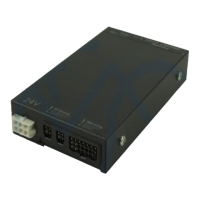
The optimum connection layout is dependent on the type of modules that are
present in the DX System. Low-current modules can be connected in series. This
provides a low-cost and simple solution.
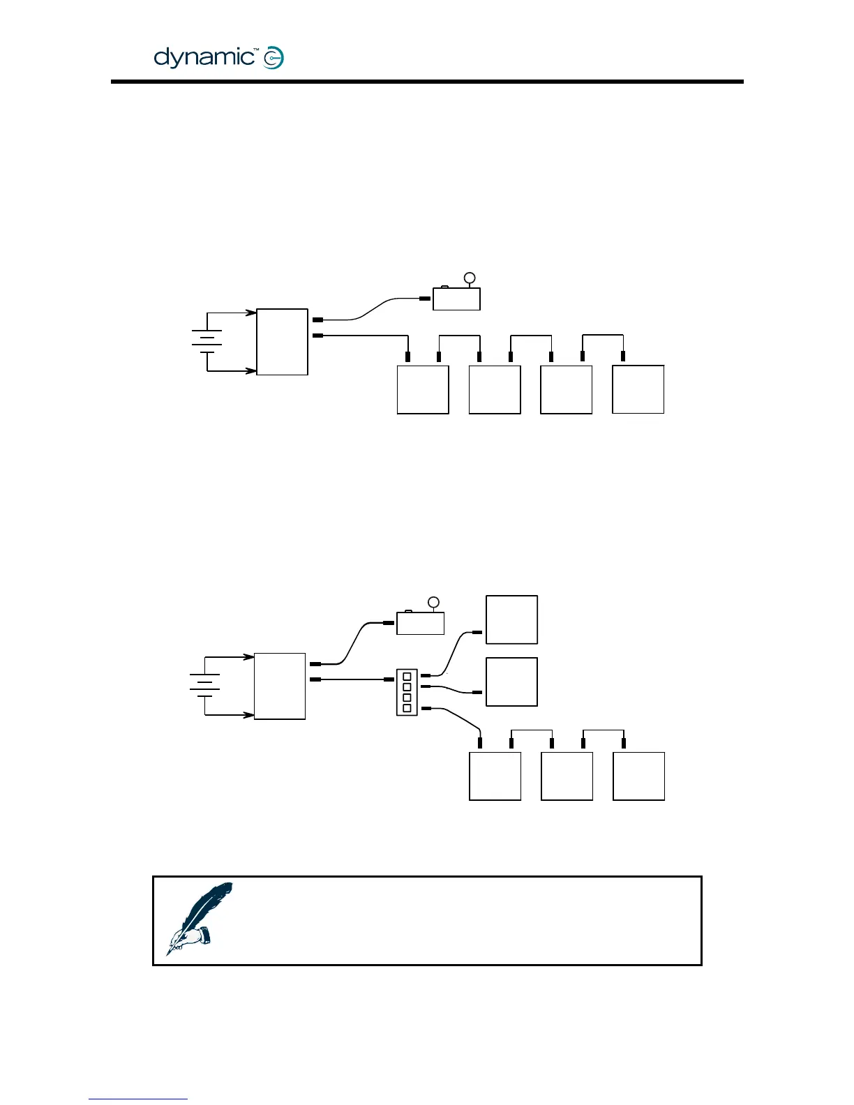
ause a voltage drop on the DX BUS when they are connected far away from the
Because of the internal resistance of the DX BUS cable, high-current modules can
c
Power Module. For this reason all high-current DX Modules (for example actuators
and lights) must be connected as close to the Power Module as possible, preferably
in parallel.
DX modules connected in series
DX Master Remote
DX
Power
Module
DX
module
DX
module
DX
module
DX
module
24V
DX BUS
DX BUS
High-current DX modules connected in parallel
24V
DX
power
module
DX BUS
DX BUS
DX
module
HIGH I
DX
module
HIGH I
DX
module
HIGH I
DX
module
LOW I
DX
module
LOW I
DX Remote
DX splitter box
DX-SKT-X4
Note:
l length of all DX BUS cables together must not exceed 15 m.
The tota
GBK60348
: Issue 1 – October 2007
28