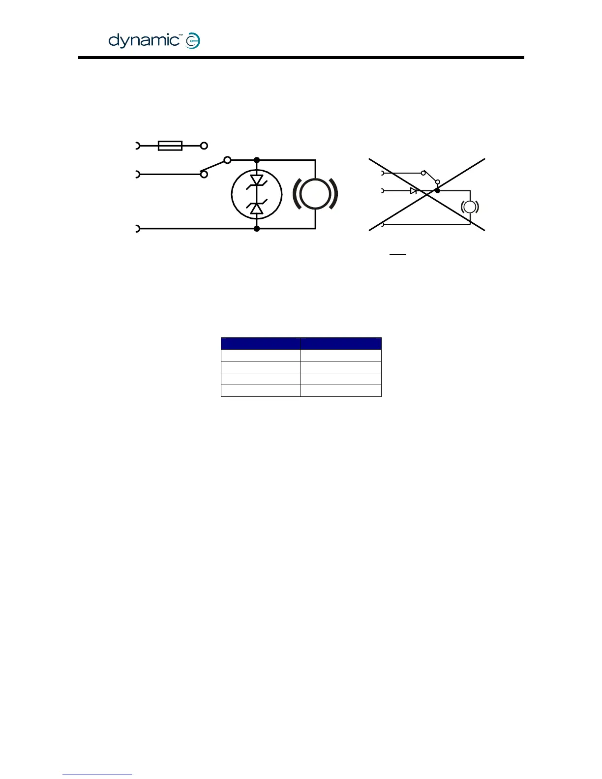
2.4.3 Manual parkbrake release switch
Manually operated parkbrake release switches must be fitted together with a suitable
suppression device across each parkbrake.
The suppression device prevents the generation of high voltage transients causing
possible damage to the Power Module or to the parkbrake release switch itself.
Some suitable suppression devices are:
Always fit a suppression device
2x zener diode
39V, min 2W
Surge: min 50W, 2ms
Park-
brake
PB+
Battery+
Fuse
Release
switch
PB-
Do NOT
connect like this
P
P
Motorola Philips
3EZ39D5 BZX70C36
3EZ36D5 BZX70C39
1N5365A BZT03C36
1N5366A BZT03C39
2.4.4 Mechanical parkbrake release
To make it possible to manually push the chair if the battery is empty, some form of
mechanical clutch or parkbrake release is required. For safety, if the parkbrake is
mechanically released the chair must not be able to drive.
One way to achieve this is to put a switch that disconnects the parkbrake from the
Power Module in the mechanical parkbrake release. When the parkbrake is
disconnected from the Power Module a Parkbrake Fault will occur and the
powerchair will not be able to drive.
2.4.5 Parkbrake operation and programming
For safety, parkbrakes are always mechanically applied in their electrical "off"-state.
This makes sure that the parkbrakes do not consume energy when the powerchair is
turned off. It also makes sure that the powerchair does not roll away if the battery
becomes empty on a slope.
To release the parkbrake, it must be "energised" (switched on), either by the Power
Module or manually with a parkbrake release switch.
• Energise a parkbrake to release it
• De-energise a parkbrake to apply the brake.
GBK60348
: Issue 1 – October 2007
22