Epson Artisan 810/835/837/710/725/730/Epson Stylus Photo PX810FW/TX810FW/PX820FWD/TX820FWD/PX830FWD/PX710W/TX710W/PX720WD/TX720WD/PX730WD/TX730WD
Revision G
DISASSEMBLY/ASSEMBLY Routing FFC/cables 197
Confidential
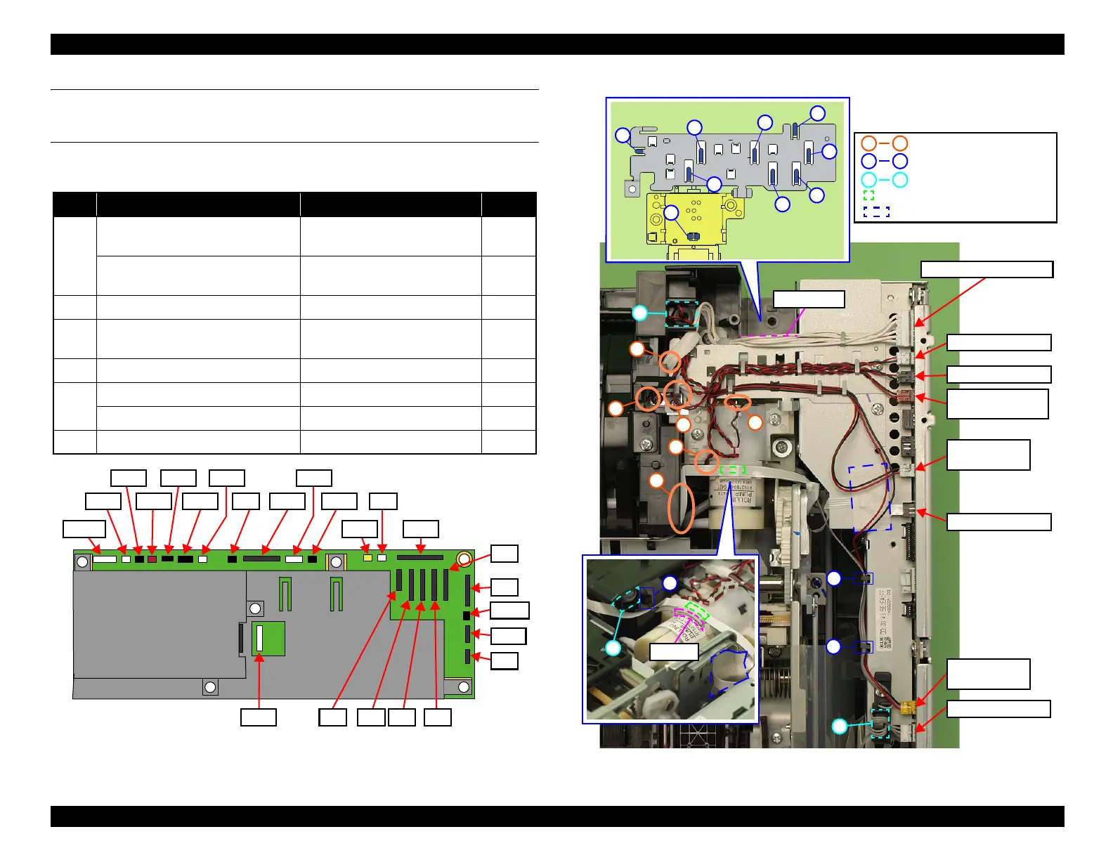
MAIN BOARD (TOP SIDE)
(ARTISAN 810/835/837/PX810FW/TX810FW/PX820FWD/TX820FWD/
PX830FWD)
The following describes the routing orders of the cables and FFCs that are connected to
the Main Board.
Figure 4-196. Connector positions on the Main Board
(Artisan 810/835/837/PX810FW/TX810FW/PX820FWD/TX820FWD/
PX830FWD)
Figure 4-197. Main Board
(Artisan 810/835/837/PX810FW/TX810FW/PX820FWD/TX820FWD/
PX830FWD)
Start Cable Route CN No.
1
PE Sensor Cable
(Ferrite core x2)
a → L → groove → I → J → b CN9
PF Encoder FFC
Double-sided tape (x1) and
Acetate tape (x2)
CN8
2 PF Motor Cable H → F → E → B CN22
3
CR Motor Cable
(Ferrite core x1)
K → c → F → E → B CN21
4 Decompression Pump Motor Cable K → F → E → B CN24
5
Duplex Unit Sensor Cable G → D → C CN13
Photo Tray Sensor Cable G → D → C → I → J CN12
6 Power Supply Unit Cable Align it to standard line → A CN501
CN501
CN22
CN21
CN24
CN49
CN25
CN13
CN41 CN10
CN51
CN12
CN9
CN6 CN4 CN3 CN2
CN1
CN36
CN5
CN31
CN7
CN32
CN8
Note * : Artisan 837/PX830FWD only
CN19*
I
J
Hook
Double-sided tape
Power Supply Unit Cable
PF Motor Cable
CR Motor Cable
Decompression
Pump Motor Cable
Duplex Unit
Sensor Cable
PE Sensor Cable
Photo Tray
Sensor Cable
Standard line
1
2
3
4
5
6
b
c
A L
a c
Ferrite core position
Routing hole for the FFC/cable
1 6
Acetate tape
PF Encoder FFC

 Loading...