5. End Effectors Part 1: Setup & Operation
20
Do not move the upper-limit mechanical stop which is on the lower side of the shaft.
Use a split muff coupling with an M4 bolt or larger to attach an end effector to the shaft.
You can use the flat cut and conical hole on the end of the shaft to orient Joint #4 by
tightening a setscrew.
The electromagnetic brake is applied to Joint #3 when the power is off. Joint #3 cannot
be raised or lowered by hand when the brake is engaged. This prevents Joint #3 from
descending under the weight of the end effector and striking any peripheral equipment
and the like when the power is cut during robot operation or when the power is on but in
the MOTOR OFF condition.
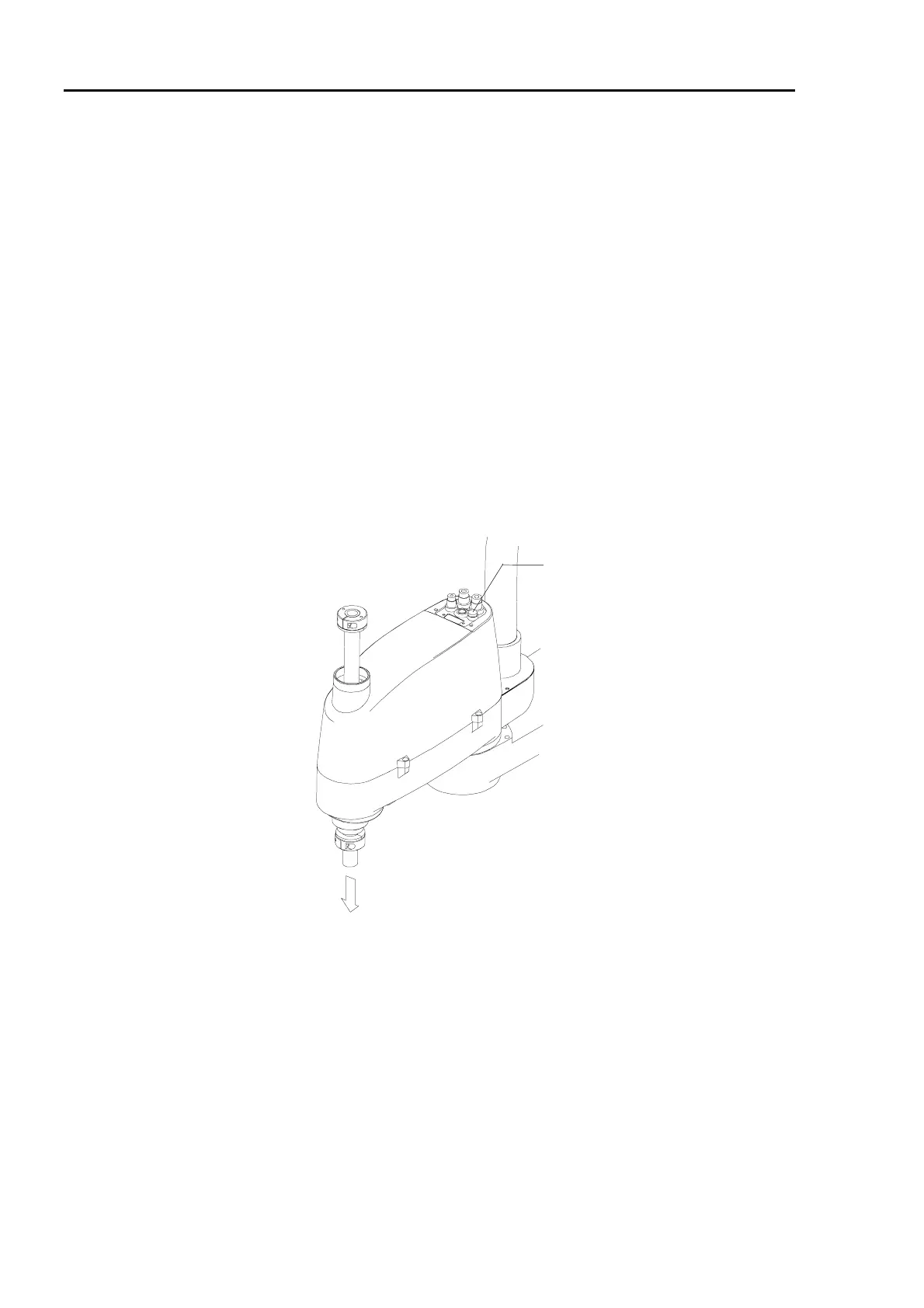
If you want to raise and lower Joint #3 when you are attaching an end effector, turn ON the
controller and keep on the Joint #3 brake release button pushing. This button is a momentary
type which releases the brake only while it is pushed.
Joint #3 descends under it own weight while you are pushing the Joint #3 brake release button.
Joint #3 brake release button
Joint #3 may descend due to the weight of the end effector.
Figure 11. Joint #3 brake release button
NOTE
NOTE
 Loading...


