11. Calibration Part 2: Maintenance
192
11.3 Calibration for SRC-3** Controllers
Refer to the SPEL for Windows online help for details on the commands used in this
section.
Common procedure for calibration
For both the ES and EL series manipulator, calibration steps (1) to (10) are the same for all
four axes.
(1) Turn ON the power of the controller after moving all axes into the motion range.
Confirm that an error occurs. If an error does not occur, proceed to next step.
Error 195 occurs when the capacitor in the motor encoder is insufficiently charged
because, for example, the motor is new. To change the capacitor, leave the power ON
for 3 or more minutes.
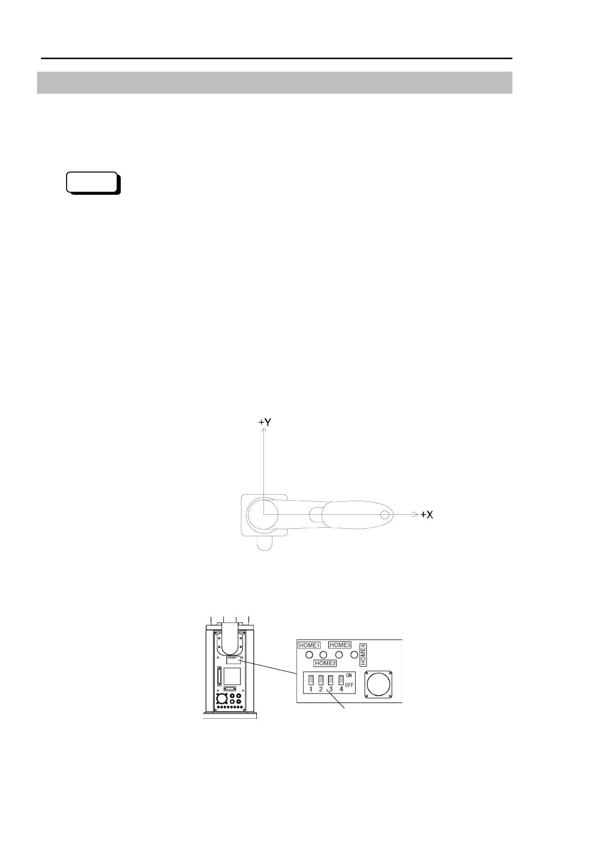
(2) Manually move axes to be calibrated into approximately the 0 pulse position.
Axis #1 : 0 pulse position : aligned with X-axis in robot coordinate system
(See the figure below).
Axis #2 : 0 pulse position : parallel with Arm #1 (i.e., straight) regardless of axis
#1 direction.
Axis #3 : 0 pulse position : uppermost position in working area.
Axis #4 : 0 pulse position : flat surface on shaft tip facing in the top of arm #2
direction.
(Rear)
(3) Open the acrylic plate on the sensor monitor on the base connector plate.
DIP switch
Sensor monitor
For protected models, remove four bolts (M3×8) from the encoder reset cover and open the
cover on the base connector plate. The encoder reset cover has an O-ring that must not to
be lost. (Refer to Sealing the Manipulator in chapter 13. Protected Model Maintenance.)
300
)
NOTE
 Loading...


