8. Motion Range and Robot Coordinates Part 1: Setup & Operation
46
(2) Changing motion range using mechanical stops
Mechanical stops physically limit the absolute area that the manipulator can move. You
can change the angle of the stops to the angles shown in the following table to limit motion
range for Joints #1 to #3 of Standard model and Joints #1 and #2 of the Clean model.
Joint Manipulator Possible area setting using the mechanical stops
ES***S/C
+125° +95° +65° +35° +5°
-5° -35° -65° -95° -125°
#1
EL***S/C
+130° +100° +70° +40° +10°
-10° -40° -70° -100° -130°
#2
E****S/C
+140° +120° +95°
-95° -120° -140°
#3
E****S
less than the maximum stroke*
When you change the position of the mechanical stops, you must also input the
corresponding pulse range.
The methods of changing area settings using the mechanical stops are shown below.
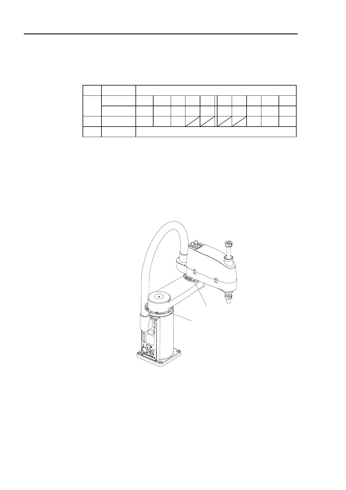
Changing the mechanical stop positions for Joint #1 and #2
Both Joint #1 and Joint #2 has threaded holes in positions corresponding to the angles for
stop settings. You can change the positions of the mechanical stops by setting bolts in the
appropriate holes. The positions of the mechanical stops are shown below.
Mechanical stop of Joint #2
Mechanical stop of Joint #1
Figure 28. Locations of the mechanical stops
 Loading...


