5. Replacing the Motors Part 2: Maintenance
116
5.3 Replacing the Joint #3 Motor
CAUTION
A brake is provided for the Joint #3 motor. If the motor is replaced, it is
necessary to adjust the brake, but be careful not to stretch the board spring of
the brake. When removing the rotor hub from the body of the brake, don’t pull
in the joint direction. Always remove it from the side.
A brake is provided for the Joint #3 motor to prevent the end effector from moving down
due to its own weight when the power is turned OFF or the motor is turned OFF. This
brake will not work while the Joint #3 motor is being replaced. Therefore, lower Joint #3
to its lower limit in advance. Joint #3 operates while the Joint #3 brake release button is
pushed with the power turned ON (See Figure 11 in the chapter End Effectors in Part 1.)
Lower Joint #3, taking care that the end effector does not strike against peripheral
equipment. Turn OFF the power before replacing the Joint #3 motor.
Removal : Joint #3
(1) Open the arm top cover and arm bottom cover. (Refer to chapter 2. Opening the
Covers.)
(2) Cut off the wire ties which fasten the Joint #3 motor and cables.
(3) Disconnect the connectors, X131, X31, and X32. To disconnect X131, pull it out
while pushing the presser tongue next to the connector number on the motor side.
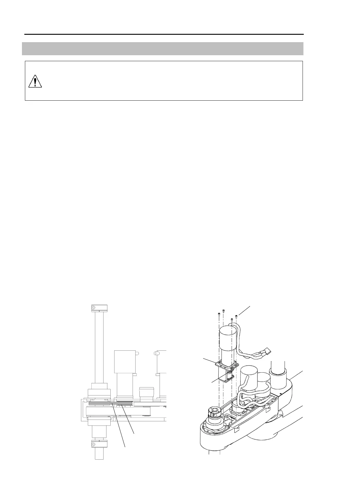
(4) Remove the four bolts (M4
×
10) from the motor plate and remove the pulley from the
Z belt. Then, pull the Joint #3 motor unit upward.
Pulley
Z belt
M4×10
Motor plate
Pulley
NOTE
 Loading...


