6. Replacing the Reduction Gear Units Part 2: Maintenance
130
6.1 Replacing the Joint #1 Reduction Gear Unit
* For protected models, contact the suppliers since the following procedure will not
apply.
Removal : Joint #1
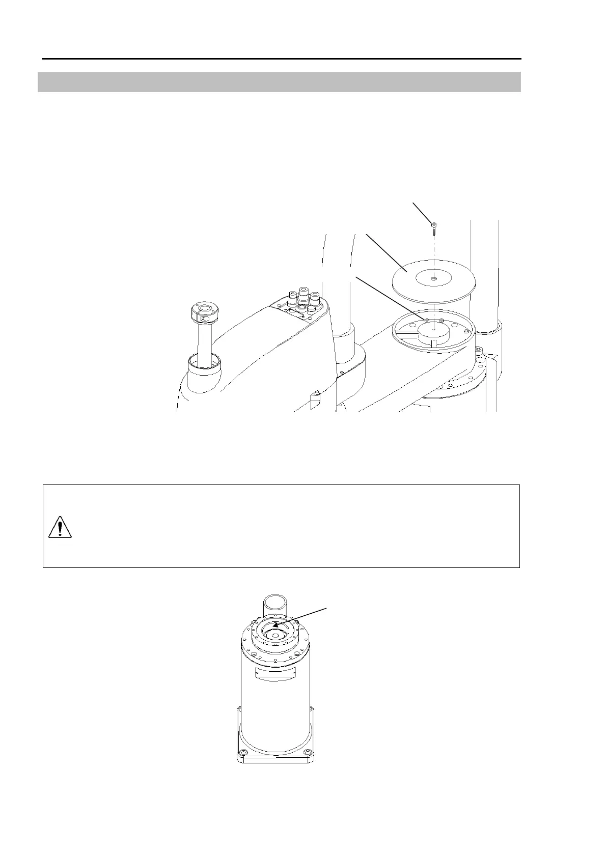
(1) Remove the bolt (M4×8) from the Joint #1 cover and remove the cover.
(2) Arm #1 fastening screw
(1) M4×8
Joint #1 cover
(2) Support the arm with more than one person. While the arm is being supported, have
another person unscrew the eight fastening bolts (M4×40 for the ES series; M5×55 for
the EL series) and remove Arm #1.
CAUTION
When removing or installing Arm #1, there must be two or more people to work
on it so that at least one of them can support the arm while others remove the
bolts and so on. The arm will drop immediately when the fastening bolts are
removed. This is highly dangerous. Also, it may cause damage or
malfunction if the arm is dropped or hit at this time.
Joint #1 reduction gear unit
Place the removed arm gently on the floor.