Part 1: Setup & Operation 4. User Wires and Pneumatic Tubes
17
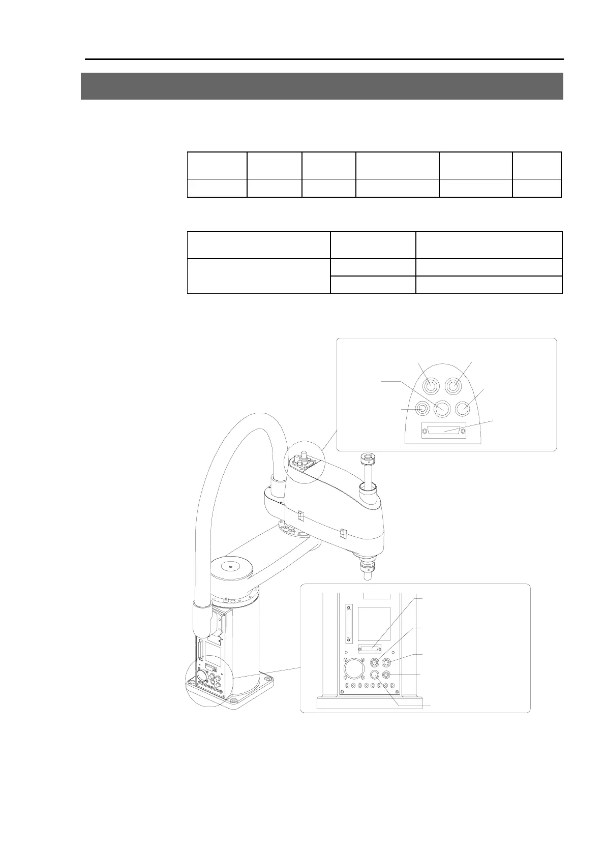
4. User Wires and Pneumatic Tubes
Electrical wires and pneumatic tubes have been incorporated into the cable unit for your
use.
Electrical wires
Rated
voltage
Allowable
current
Number of
cables
Nominal sectional
area
Outer diameter Note
AC/DC30 V 1 A 15 0.211 mm
2
φ 8.3±0.3 mm
Shielded
Compatible connector: 15-pin D-sub connector. Pins with the same number are connected.
Pneumatic tubes
Max. usable pneumatic pressure
Number of
pneumatic tubes
Outer diameter × Inner diameter
2
φ 6 mm × φ 4 mm
0.59MPa (6kgf/cm
2
)
1
φ 4 mm × φ 2.5 mm
The ends of each pneumatic tube are equipped with fittings for connecting pneumatic tubes
having an outer diameter of φ 6 mm and φ 4 mm.
Fitting (white)
for
φ
6 tube
Spare
15-pin D-sub
connector
Joint #3 Brake
release button
Fitting (black)
for
φ
6 tube
Fitting
for
φ
4 tube
15-pin d-sub connector
Fitting (black) for
φ
6 tube
Fitting (white) for
φ
6 tube
Fitting for
φ
4 tube
Spare
* If the manipulator is a Clean model, refer to chapter 11. Clean Model.
* If the manipulator is a Protected model, refer to chapter 12. Protected Model.
Figure 9. User wires and tubes
 Loading...


