Part 1: Setup & Operation 6. Attaching a Camera, Valve, and Other Devices
31
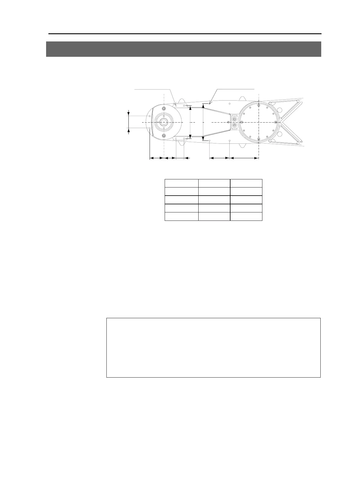
6. Attaching a Camera, Valve, and Other Devices
Arm #2 has eight threaded holes. Use these holes for attaching cameras, valves, and other
equipment. See Figure 10 in 7. External Dimensions for information on dimensions.
A:6-M4 depth 8
B:4-M4 depth 8
108(EL)
92(ES)
30
82
20
72(ES)
82(EL)
50 30 35
Height from the base-installed surface
A B
ES***S 378 383
ES***C/P 379 384
EC***S 399 404
EC***C/P 400 405
Figure 19. Position of threaded holes in Arm #2
(bottom side)
[unit: mm]
When you attach a load to the arm, you must consider WEIGHT parameters as explained in
the section 5.2. When you attach a camera or other devices to the shaft, enter the total
weight of the end effector, work piece and the attached device to the parameter. When you
attach a camera or other device to the arm, calculate the weight as equivalent weight of
Joint #3, add this to the load weight.
Refer to section 5.2 The end effector and acceleration / deceleration for details on
WEIGHT parameters.
Equivalent weight is found using the formula below.
When you attach the equipment near Joint #2 : W
M
= M (L
1
)
2
/ (L
1
+L
2
)
2
When you attach the equipment to the end of Arm #2 : W
M
= M (L
M
)
2
/ (L
2
)
2
W
M
: equivalent weight
M : weight of camera, etc.
L
1
: length of Arm #1
L
2
: length of Arm #2
L
M
: distance form rotation center of Joint #2 to center of gravity of camera, etc.
<Example> A 1kg camera was attached to the end of the arm (340 mm from the rotation
center of Joint #2) of an ES with a load weight of W = 2kg.
M = 1, L
2
= 235, L
M
= 340
W
M
= 1 × 340
2
/ 235
2
= 2.09 → 2.1 (rounded up)
W + W
M
= 2 + 2.1 = 4.1
Enter 4.1 as WEIGHT parameter. Refer to section 5.2 for the method of
setting WEIGHT parameter.
 Loading...


